A broadband photodetector responsivity tester and its test method
A technology of photodetectors and testing methods, applied in the direction of instruments, etc., can solve the problem that the responsivity measurement of ultra-bandwidth photodetectors cannot be satisfied, the frequency sweep method cannot get rid of the extra calibration of electro-optical conversion devices, and the signal ratio and dynamic range of the intensity-to-noise method are small etc. to achieve the effect of realizing self-referencing measurement, ensuring self-referencing measurement, improving system signal-to-noise ratio and dynamic range
- Summary
- Abstract
- Description
- Claims
- Application Information
AI Technical Summary
Problems solved by technology
Method used
Image
Examples
Embodiment 1
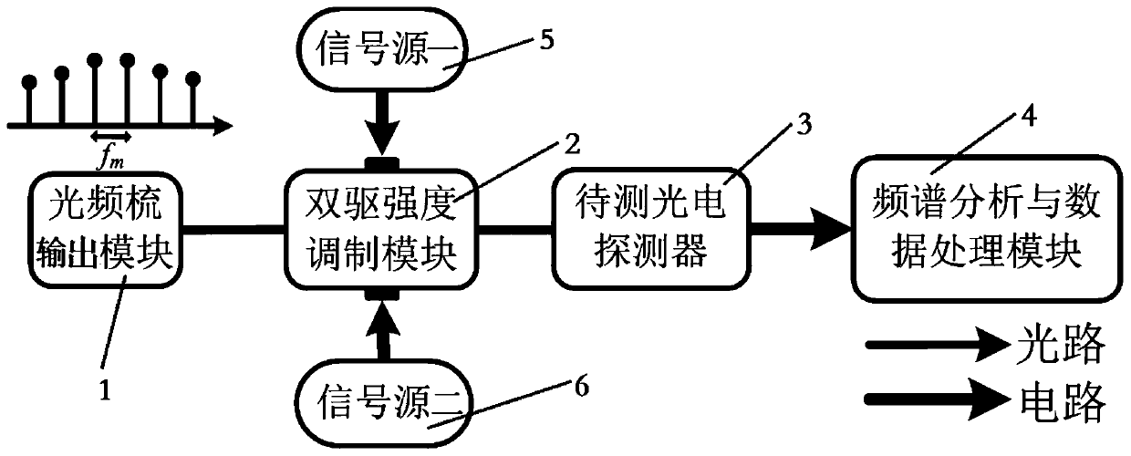
[0048] The optical frequency comb output module in this embodiment adopts a mode-locked laser with a repetition frequency of 10 GHz, the dual-drive intensity modulation module adopts a dual-drive Mach-Zehnder modulator, and the frequency of setting signal source 1 to output a sinusoidal microwave signal is 3.01 GHz, and the signal The frequency of the sinusoidal microwave signal output by the second source is 3GHz, and the optical signal output by the dual-drive intensity modulation module is converted into an electrical signal by the photodetector under test, which is analyzed and measured by the spectrum analysis and data processing module.
[0049] When k=0, the measurement frequency is 6.01GHz (f 1 +f 2 ), 0.01GHz (f 1 -f 2 ) amplitude values, respectively A(f 1 +f 2 )=0.0041V, A(f 1 -f 2 ) = 0.0038V, then according to (4) formula, the photodetector to be tested can be obtained at a frequency of 6.01GHz (f 1 +f 2 ) and 0.01GHz (f 1 -f 2 ) ratio of responsiveness ...
Embodiment 2
[0053] The optical frequency comb output module in this embodiment adopts a mode-locked laser with a repetition frequency of 10 GHz, the dual-drive intensity modulation module adopts a dual-drive Mach-Zehnder modulator, and the frequency of setting signal source 1 to output a sinusoidal microwave signal is 3.81 GHz, and the signal The frequency of the sinusoidal microwave signal output by the second source is 3.8 GHz. The optical signal output by the dual-drive intensity modulation module is converted into an electrical signal by the photodetector to be tested, which is analyzed and measured by the spectrum analysis and data processing module.
[0054] When k=1, the measurement frequency is 17.61GHz (f m +f 1 +f 2 ), 10.01GHz (f m +f 1 -f 2 ) amplitude values, respectively A(f m +f 1 +f 2 )=0.0036V, A(f m +f 1 -f 2 )=0.0029V, then according to formula (4), it can be obtained that the photodetector to be tested is at a frequency of 17.61GHz (f m +f 1 +f 2 ) and 10....
Embodiment 3
[0063] The optical frequency comb output module in this embodiment adopts a mode-locked laser with a repetition frequency of 10 GHz, and the dual-drive intensity modulation module adopts a dual-drive Mach-Zehnder modulator. The frequency of setting signal source 1 to output a sinusoidal microwave signal is 4.51 GHz, and the signal The frequency of the sinusoidal microwave signal output by the second source is 4.5 GHz. The optical signal output by the dual-drive intensity modulation module is converted into an electrical signal by the photodetector under test, which is analyzed and measured by the spectrum analysis and data processing module.
[0064] When k=2, the measurement frequency is 29.01GHz (2f m +f 1 +f 2 ), 20.01GHz (2f m +f 1 -f 2 ) amplitude values, respectively A(2f m +f 1 +f 2 )=0.0031V, A(2f m +f 1 -f 2 )=0.0021V, then according to formula (4), the photodetector to be tested can be obtained at a frequency of 29.01GHz (2f m +f 1 +f 2 ) and 20.01GHz (2...
PUM
 Abstract
Description
Claims
Application Information
 - R&D
- Intellectual Property
- Life Sciences
- Materials
- Tech Scout
- Unparalleled Data Quality
- Higher Quality Content
- 60% Fewer Hallucinations
Browse by: Latest US Patents, China's latest patents, Technical Efficacy Thesaurus, Application Domain, Technology Topic, Popular Technical Reports.
© 2025 PatSnap. All rights reserved.Legal|Privacy policy|Modern Slavery Act Transparency Statement|Sitemap|About US| Contact US: help@patsnap.com


