Underwater vehicle structure internal stress wave dynamic display system and method

A technology for underwater vehicles and internal stress, applied in the testing of machines/structural components, fluid dynamics tests, instruments, etc. sequence, easy to install, and widen the effect of application scenarios

Active Publication Date: 2021-03-23
CHINA ACAD OF LAUNCH VEHICLE TECH
View PDF10 Cites 0 Cited by
  • Summary
  • Abstract
  • Description
  • Claims
  • Application Information

AI Technical Summary

Problems solved by technology

[0008]The photoelastic imaging experiments above have studied the photoelastic target with a planar geometry, but it is not yet possible to analyze the internal stress of the underwater vehicle structure with a geometry of gyrations. fine-grained imaging

Method used


Image

  • Underwater vehicle structure internal stress wave dynamic display system and method
  • Underwater vehicle structure internal stress wave dynamic display system and method
  • Underwater vehicle structure internal stress wave dynamic display system and method

Examples


Embodiment

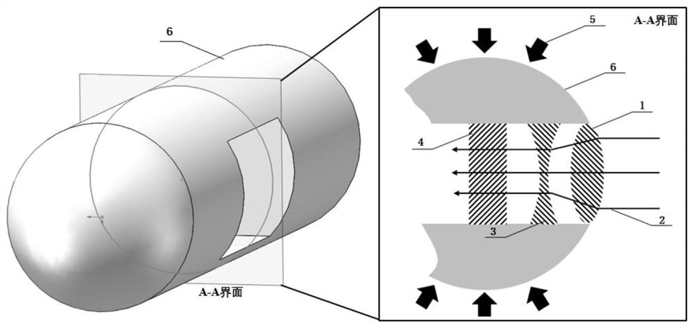
[0049]The optical path system is the core part of the internal stress wave display technology of underwater navigation workpiece under the airborne load.figure 1 A schematic diagram of the surface of the surface of the surface and its internal optical components thereof is given. The stress-light refractive theory and the principle of polarization interference are limited, and the optical projectment system requires incident light to be parallel to the light source, and the light source incident surface and transmission surface of the underwater navigation workpiece must be a planar structure, but underwater navigation workpiece The main body portion (matrix) is a typical swing curved surface structure, which does not meet the above technical requirements of the existing dynamic optical exposure imaging system. In order to solve the above problems, the embodiment of the underwater navigation workpiece 6 having a diameter of 40 mm is cut out of the cross section of 20 mm × 20 mm in t...


PUM


Abstract

An underwater vehicle structure internal stress wave dynamic display system comprises an underwater vehicle workpiece, a cavitation water tunnel, a light path system, a bright and dark stripe image acquisition system and a stress wave image post-processing system. The underwater vehicle workpiece simulates an underwater vehicle of which the geometrical form is a revolving body. The cavitation water tunnel provides a navigation environment for the underwater vehicle workpiece. The light path system provides a transient laser light source. The bright and dark stripe image acquisition system acquires a bright and dark stripe image presented on a photoelastic material in the underwater vehicle workpiece during cavitation, and sends the bright and dark stripe image to the stress wave image post-processing system. The stress wave image post-processing system performs quantitative analysis on the bright and dark stripe image, performs decoupling to obtain transverse waves, longitudinal wavesand Rayleigh waves in the underwater vehicle workpiece, and obtains the wavelength, propagation speed and spatial distribution coordinates of each wave pattern. The invention further provides a dynamic display method. According to the invention, refined measurement of stress waves is realized, and the limitation that a traditional photoelastic imaging technology is only suitable for a planar structure is broken through.

Description

Technical field[0001]The present invention relates to a stress wave dynamic display technique, and more particularly to an internal stress waveform display system and method for the water underwater navigation structure under water.Background technique[0002]Circulation load is one of the classic and frontier problems of high-speed hydropower, including blade, air suspenders, jet, water jet, and collapsed shock waves, have strong instantaneous times, multi-scale Typical features such as strong impact, forcing the solid medium inside the navigation structure to be forced to vibrate and propagate in the form of complex stress waves. Structural stress wave induced the structure of structural vibration, noise, air erosion, etc. The process is conducive to pushing the overall improvement of underwater navigation water load control technology.[0003]At home and abroad, existing dynamic light imaging methods can perform full-scale imaging of stress wave inside the planar solid structure, and...

Claims


Application Information

Patent Timeline
Patent Type & Authority Applications(China)
IPC IPC(8): G01M10/00
CPCG01M10/00
Inventor 李明马潇健俞启东姚星合徐志程赵静王大鹏潘姝
Owner CHINA ACAD OF LAUNCH VEHICLE TECH
Why Eureka
Try Eureka