Main cable strand anchoring device of suspension bridge

An anchoring device and suspension bridge technology, which is applied to bridges, bridge parts, bridge construction, etc., can solve the problem that the main cable anchoring device is no longer applicable, and achieve the effect of simple and reliable force bearing, simple construction process and clear force transmission path.

Pending Publication Date: 2019-03-08
CCCC FIRST HIGHWAY CONSULTANTS
View PDF5 Cites 3 Cited by
  • Summary
  • Abstract
  • Description
  • Claims
  • Application Information

AI Technical Summary

Problems solved by technology

[0004] The purpose of the present invention is to provide a kind of main cable strand anchoring device of suspension bridge, solve the problem that the main cable anchoring device of PPWS method is no longer applicable

Method used


Image

  • Main cable strand anchoring device of suspension bridge
  • Main cable strand anchoring device of suspension bridge
  • Main cable strand anchoring device of suspension bridge

Examples


Embodiment 1

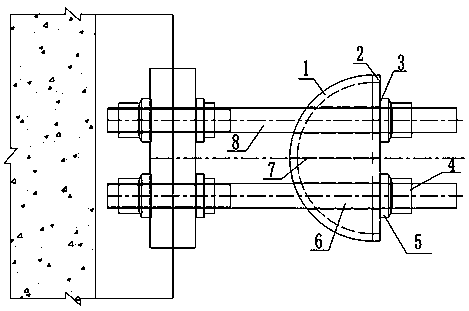
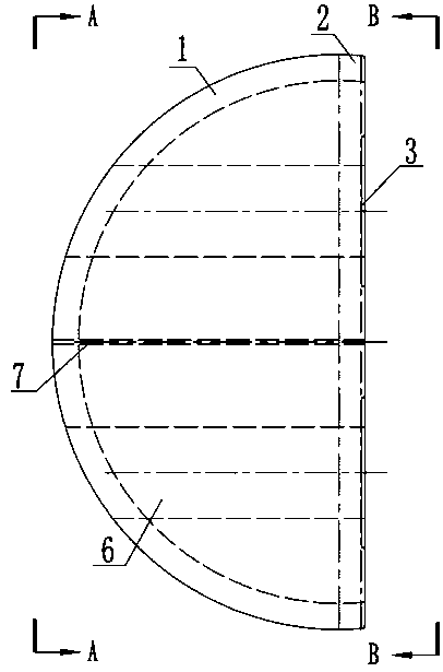
[0035] The radius of the outer arc of the thigh boot is 80d to 100d (d is the diameter of the steel wire), the horizontal length of the part beyond the semicircular arc is 20 to 100mm, the radius of the bottom of the groove is 70d to 90d, and the thickness of the boot is 400 to 600mm.

[0036] Two grooves are arranged, and the section is arranged in a trapezoidal shape. The distance between the edge of the groove and the edge of the femoral boot is 10-50mm.

[0037] The hole diameter of the tie rod of the stock shoe is 10-20mm larger than the diameter of the tie rod, the hole is arranged near the quarter point, and the depth of the notch of the gasket is 4-10mm. The diameter of the hole in the center of the thigh boot is 6-10 mm.

[0038] Perforations with a diameter of 20-40mm are respectively opened on the outer sides of the openings of the two tie rods to meet the needs of temporary anchoring and construction hoisting.

Embodiment 2

[0040] The radius of the outer arc of the thigh boot is 80d to 100d (d is the diameter of the steel wire), the horizontal length of the part beyond the semicircular arc is 20 to 100mm, the radius of the bottom of the groove is 70d to 90d, and the thickness of the boot is 400 to 600mm.

[0041] Two grooves are arranged, and the cross-section is arranged in a rectangle. The distance between the edge of the groove and the edge of the femoral boot is 10-50mm.

[0042] The hole diameter of the tie rod of the stock shoe is 10-20mm larger than the diameter of the tie rod, the hole is arranged near the quarter point, and the depth of the notch of the gasket is 4-10mm. The diameter of the hole in the center of the thigh boot is 6-10 mm.

[0043] Set 2 to 4 screw holes between M20 and M48 on both sides of the stock boot to meet the needs of temporary anchoring and hoisting during construction.

Embodiment 3

[0045] The radius of the outer arc of the thigh boot is 80d to 100d (d is the diameter of the steel wire), the horizontal length of the part beyond the semicircular arc is 20 to 100mm, the radius of the bottom of the groove is 70d to 90d, and the thickness of the boot is 400 to 600mm.

[0046] Two grooves are arranged, and the section is arranged in a trapezoidal shape. The distance between the edge of the groove and the edge of the femoral boot is 10-50mm.

[0047] The hole diameter of the tie rod of the stock shoe is 10-20mm larger than the diameter of the tie rod, the hole is arranged near the quarter point, and the depth of the notch of the gasket is 4-10mm. The diameter of the hole in the center of the thigh boot is 6-10 mm.

[0048] Set 2 to 4 screw holes between M20 and M48 on both sides of the stock boot to meet the needs of temporary anchoring and hoisting during construction.


PUM


Abstract

The invention relates to a main cable strand anchoring device of a suspension bridge, which comprises a strand boot, a pull rod and a pull rod anchoring assembly; the strand boot is a semi-cylindricalblock structure, which comprises a circular arc surface, semicircular surfaces on both sides and a rectangular surface on the opposite side of the circular arc surface; a plurality of strand boot grooves for locating and winding steel wires are formed in the circular arc surface of the strand boot, and the track of the strand boot grooves is parallel to the outer arc of the strand boot; the strand boot is provided with a pull rod opening perpendicular to the rectangular surface; the pull rod passes through the pull rod opening, wherein one end of the pull rod is anchored to the front anchor surface by the pull rod anchoring assembly, and the other end is fixed to the rectangular surface of the strand boot by the pull rod anchoring assembly. According to the main cable strand anchoring device of the suspension bridge, the anchoring problem of the main cable strand of an AS-method suspension bridge can be solved, and has the advantages of clear route of transmission force, simple and reliable force, in line with the construction process of the main cable strand of the AS-method suspension bridge, and the construction technology is simple and convenient.

Description

technical field [0001] The invention belongs to the technical field of suspension bridge structures, and in particular relates to an anchoring device for main cable strands of a suspension bridge. Background technique [0002] At present, there are two main methods for erecting the main cables of suspension bridges: the aerial spinning method (AS method) and the prefabricated parallel wire strand method (PPWS method). The AS method refers to the method of using the steel wire as the traction unit, weaving multiple steel wires into a steel wire strand on the catwalk, and then binding the strands to form the main cable; the PPWS method uses the strand as the traction unit, and then the cable A method of bundling strands to become the main cable. At present, the PPWS method is used in my country to erect the main cable strands of suspension bridges, while the aerial spinning method (AS method) has no construction precedent in mainland China. [0003] Due to the heavy main cab...

Claims


Application Information

Patent Timeline
Patent Type & Authority Applications(China)
IPC IPC(8): E01D19/14E01D19/16
CPCE01D19/14E01D19/16
Inventor 冯云成翟晓亮刘冠华牛祥恒豆飞杨宇豪宋松林张延龙吴永昌王江波李永庆付炳宁闫生龙
Owner CCCC FIRST HIGHWAY CONSULTANTS
Why Eureka
Try Eureka