
A device and method for tensile testing of brittle tendons

A technology of tensile test and reinforcement, applied in the direction of measuring device, applying stable tension/pressure to test material strength, analyzing material, etc., can solve problems such as cross-section damage, achieve simple device, save test cost, and convenient operation Effect

Active Publication Date: 2015-11-18
JINLING INST OF TECH
View PDF5 Cites 0 Cited by
  • Summary
  • Abstract
  • Description
  • Claims
  • Application Information

AI Technical Summary

Problems solved by technology

The clamping of the clamping block may cut the tendon transversely, at least causing serious damage to the cross section, resulting in stretching process in the clamping part

Method used


Image

  • A device and method for tensile testing of brittle tendons
  • A device and method for tensile testing of brittle tendons
  • A device and method for tensile testing of brittle tendons

Examples


Embodiment Construction

[0031] A device for tensile testing of brittle tendons, comprising a casing 1, a binding nut 2, a ball-and-socket nut 3, and a ball-end tie rod 4.

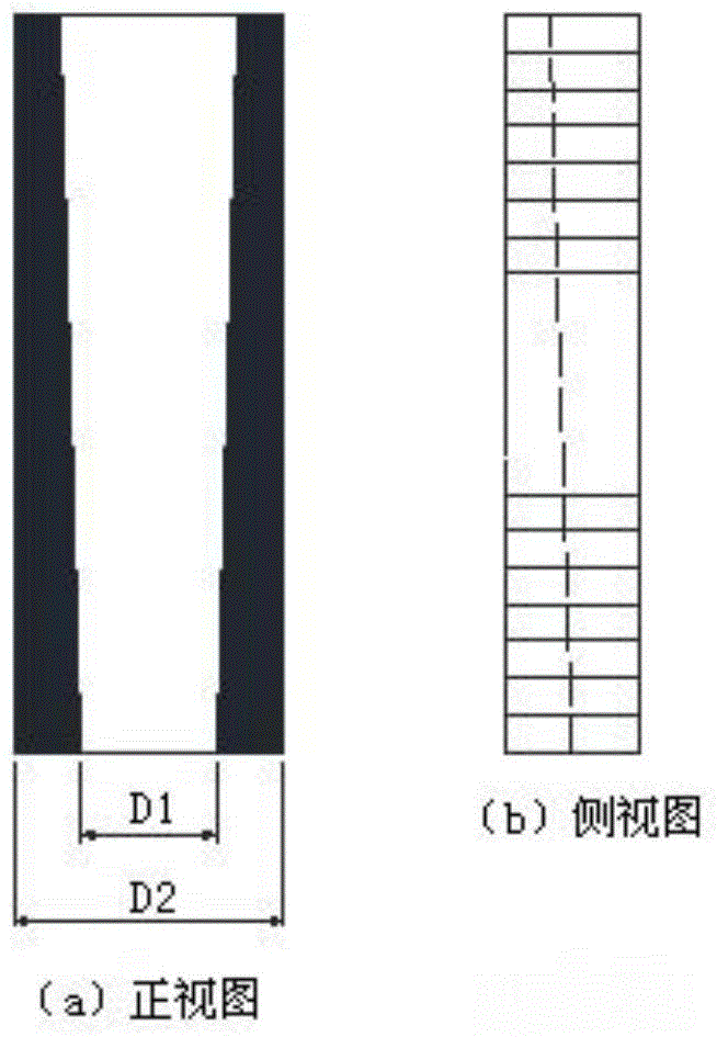
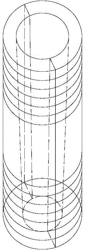
[0032] Such as figure 1 and figure 2 As shown, the casing 1 is assembled from two half-pipes, and a frustum-shaped cavity is formed inside after the assembly. The outside of the casing 1 is in the shape of a cylinder, and the surface of the cylinder is provided with external threads.

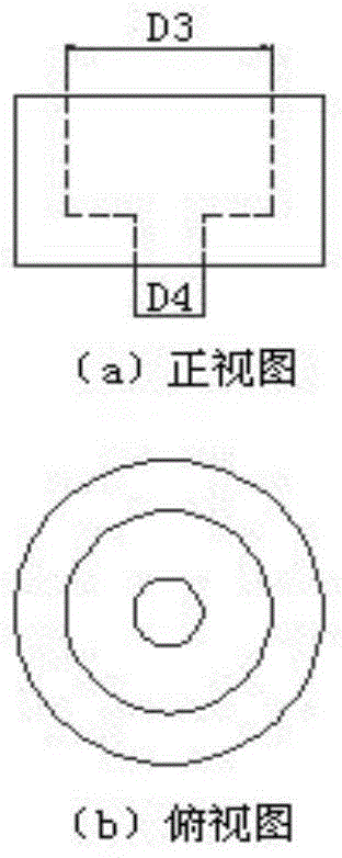
[0033] Such as image 3 and Figure 4 As shown, the binding nut 2 is screwed on the end of the sleeve 1 with a smaller inner diameter.

[0034] Such as Figure 5-7 As shown, there is a hemispherical cavity inside the ball-and-socket nut 3, one end of the ball-joint tie rod 4 is spherical, the ball-joint tie rod 4 can pass through the ball-and-socket nut 3, and the ball head at the end of the ball-joint tie rod 4 is placed in a hemispherical shape. In the cavity, it can rotate flexibly.

[0035] Such as Figure 8 As shown, after the ball joi...


PUM


Abstract

The invention provides a device and a method for a tensile test of a fragile rib material. The device comprises a sleeve 1, a binding screw cap 2, a ball socket type screw cap 3 and a ball head pull rod 4, wherein the inner part of the sleeve 1 is a circular-platform-shaped cavity and the inner diameters of the two ends of the sleeve 1 are different; the binding screw cap 2 is screwed down on the outer part of one end with the smaller inner diameter of the sleeve 1; after the ball head pull rod 4 penetrates through the ball socket type screw cap 3, the ball socket type screw cap 3 is screwed down on the outer part of one end with the larger inner diameter of the sleeve 1. When the device and the corresponding method are used for carrying out the tensile test on the fragile rib material, a test sample does not need to be directly clamped so as to protecting end parts of the test sample from being damaged by a too large transverse concentrated force; the test sample is anchored firmly and cannot be unstuck in the testing process; and the device can be used conveniently and repeatedly.

Description

technical field [0001] The invention relates to the field of testing equipment, in particular to a device and method for tensile testing of brittle bars or other non-metallic bars. Background technique [0002] For reinforced concrete structures, the corrosion of steel bars is an unavoidable problem in the long-term use process, and the damage of reinforced concrete structures is mostly caused by the corrosion of steel bars. Therefore, engineering researchers hope to replace steel bars with non-corroding steel, and fundamentally eliminate the hidden danger of steel bars being corroded. At present, there are many new types of steel bars being studied and used, including FRP bars such as glass fiber bars and basalt fiber bars. For new materials, their most basic mechanical properties must be verified through repeated tests to meet the requirements before they can be popularized and applied. [0003] Unlike steel bars, the new composite bars are mostly brittle materials, so i...

Claims


Application Information

Patent Timeline
Patent Type & Authority Patents(China)
IPC IPC(8): G01N3/02G01N3/08
Inventor 王潘绣宣卫红陈育志陈晓洪王瑶王艳
Owner JINLING INST OF TECH
Learn More