Prefabricated building and component anchoring method thereof

Pending Publication Date: 2021-11-30
夏祥军
View PDF6 Cites 0 Cited by
  • Summary
  • Abstract
  • Description
  • Claims
  • Application Information

AI Technical Summary

Problems solved by technology

[0004] In order to solve the problems of the scarcity of construction workers, the waste of a large amount of turnover materials, the inability of traditional building construction to be factory-like, the dependence on the weather, the greatly shortened construction period, and the greatly reduced construction cost, the most important thing is to solve the problems of building walls. The anchoring problem between the slab and the beam, the floor, and the column, especially solves the problem of the anchorage between the lower opening of the building wall plate and the floor and the low safety factor after the anchorage, and also solves the problems existing in the existing prefabricated buildings. To solve the problem that building wall panels, building beams, and floor slabs cannot be anchored into a unified whole, an anchoring method for prefabricated buildings and their components is invented, which is invented on the basis of current prefabricated buildings and traditi

Method used


Image

  • Prefabricated building and component anchoring method thereof
  • Prefabricated building and component anchoring method thereof

Examples


Embodiment Construction

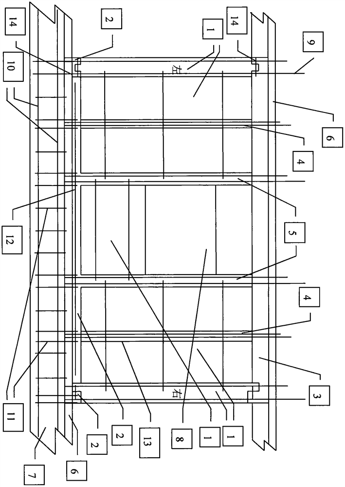
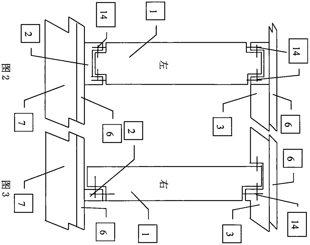
[0022] In order to make the technical means realized by the present invention, creation feature, reach purpose and effect easy to understand, the building of a full shear wall raft (strip) foundation without basement is further set forth the present invention below as an embodiment, for It is convenient to understand the anchoring methods of 2 kinds of prefabricated wall panels in the application of the present invention, figure 1 The two kinds of anchoring methods of prefabricated wall panels are illustrated by means of cross-sectional diagrams, without specific dimensioning, figure 1 The anchoring method of the prefabricated wall panel on the left adopts the anchoring method that the prefabricated wall panels with "convex" shape at both ends are respectively anchored into the inverted "concave" shaped cast-in-place concrete beam and the "concave" shaped cast-in-situ anchor beam; figure 1 The anchoring method of the prefabricated wall panel on the right adopts the method of a...


PUM


Abstract

The invention relates to a prefabricated building and a component anchoring method thereof, and belongs to the field of buildings. The prefabricated building is composed of a prefabricated wallboard, a cast-in-place anchoring beam, a cast-in-place concrete beam, a cast-in-place concrete constructional column, a cast-in-place concrete column, a cast-in-place concrete floor, a raft (strip-shaped) foundation, a window (hole), a column main reinforcement, a beam main reinforcement, a beam stirrup, a cast-in-place anchoring beam main reinforcement, a hollow pipeline, an anchoring steel bar and other components. The component anchoring method comprises the following steps of anchoring the cast-in-place concrete beam, the cast-in-place anchoring beam and the cast-in-place concrete column on the prefabricated wallboard, wherein notches are reserved in the upper and lower ends of the prefabricated wallboard, and anchoring steel bars are reserved on the side vertical surfaces; and anchoring the cast-in-place concrete beam, the cast-in-place anchoring beam and the raft (strip-shaped) foundation or the cast-in-place concrete floor at the two ends of the cast-in-place concrete constructional column on the prefabricated wallboard. The problems of long construction period, high cost, serious material waste and many potential safety hazards of construction of a traditional building are solved, and the problems of difficulty in anchoring a filler wall of the prefabricated building, infirmness in anchoring and poor corrosion resistance are also solved.

Description

Technical field: [0001] The invention relates to a prefabricated building with prefabricated construction, which is suitable for all building constructions. [0002] technical background: [0003] At present, with the rise of high-rise buildings, construction workers are becoming more and more scarce, construction costs are getting higher and higher, and there are many safety hazards in building construction. The use of traditional construction techniques not only wastes a lot of turnover materials, especially a lot of formwork, Wooden squares indirectly cause serious damage to the country's ecology. The construction is greatly affected by the weather and the construction period is long. Under this background, an anchoring method for prefabricated buildings and their components is invented, which solves the shortage of construction workers. , greatly reduce the use of turnover materials, realize factory production, reduce the dependence of building construction on weather, gr...

Claims


Application Information

Patent Timeline
IPC IPC(8): E04B1/00E04G21/14E04C2/30E04C2/06E04B1/38E04C3/20E04C3/34
CPCE04B1/00E04G21/14E04C2/30E04C2/06E04B1/38E04C3/20E04C3/34
Inventor 夏祥军
Owner 夏祥军
Why Eureka
Try Eureka