
Lighting equipment with monitoring function for rotating machine under radiation environment

A technology of rotating machinery and radiation environment, applied in lighting and heating equipment, lighting devices, lighting devices, etc., can solve the problems of inability to ensure internal cleanliness, inability to monitor the cleaning of institutions, and poor quality of shooting images, and achieve low pressure and openness. The effect of low tightening force and improved safety

Inactive Publication Date: 2019-03-08
DONGGUAN UNIV OF TECH
View PDF6 Cites 2 Cited by
  • Summary
  • Abstract
  • Description
  • Claims
  • Application Information

AI Technical Summary

Problems solved by technology

[0004] The purpose of the present invention is to provide a lighting device with a monitoring function for rotating machinery in a radiation environment, so as to solve the problem that the existing lighting device proposed in the background technology cannot only adjust the height, which makes it difficult to monitor the device when it fails. At the same time, it is difficult to clean the interior, and the cleanliness of the interior cannot be guaranteed. It has little functionality. It can only illuminate the rotating machinery but cannot monitor it. It is troublesome, and the monitoring mechanism cannot be cleaned, resulting in a long-term The problem of poor picture quality after use

Method used


Image

  • Lighting equipment with monitoring function for rotating machine under radiation environment
  • Lighting equipment with monitoring function for rotating machine under radiation environment
  • Lighting equipment with monitoring function for rotating machine under radiation environment

Examples


Embodiment Construction

[0026] The following will clearly and completely describe the technical solutions in the embodiments of the present invention with reference to the accompanying drawings in the embodiments of the present invention. Obviously, the described embodiments are only some, not all, embodiments of the present invention. Based on the embodiments of the present invention, all other embodiments obtained by persons of ordinary skill in the art without making creative efforts belong to the protection scope of the present invention.

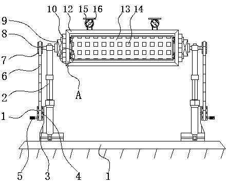
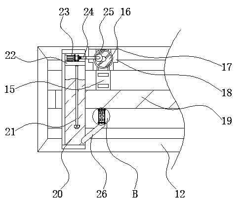
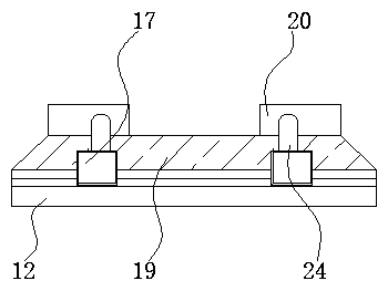
[0027] see Figure 1-5, the present invention provides a technical solution: a lighting device with monitoring function for rotating machinery in a radiation environment, including a base 1, a driven gear 7 and a housing 12, and a first hydraulic rod 2 is installed above the base 1 , and the left side of the first hydraulic rod 2 is fixed with an extension block 3, the space between the first hydraulic rod 2 and the extension block 3 is stamped, and the left s...


PUM


Abstract

The invention discloses lighting equipment with a monitoring function for a rotating machine under a radiation environment. The lighting equipment comprises a substrate, driven gears and an outer shell. First hydraulic rods are installed on the substrate. The first hydraulic rods and extending blocks are formed in a punching manner. The left side of each drive gear is provided with a handle, the right side of each driven gear is connected with a rotating shaft. The surface of the left end of each thermal baffle is fixedly provided with a screw. The rear part of the outer shell is fixedly provided with a back plate. A liquid storage tank is internally provided with a water inlet pipe. According to the lighting equipment with the monitoring function for the rotating machine under the radiation environment, by means of the first hydraulic rods, the outer shell, the thermal baffles and a light emitting diode, the first hydraulic rods extend and retract to drive the outer shell to adjust the position in the vertical direction, and therefore the equipment is driven to ascend or descend; and after the outer shell descends, the interior of the outer shell can be washed, or parts in the outer shell can be maintained or changed, and steps needed for washing, maintaining or changing the equipment are simplified.

Description

technical field [0001] The invention relates to the technical field of illumination of rotating machinery in a radiation environment, in particular to an illumination device with a monitoring function for a rotating machinery in a radiation environment. Background technique [0002] Radiation refers to the phenomenon that a part of the electromagnetic energy from the field source breaks away from the field source and propagates far away, and then returns to the field source. The energy diffuses outward in the form of electromagnetic waves or particles. Radiation itself is a neutral term, but some The radiation of substances may cause harm. Rotating machinery is mainly divided into two types, one is the microcomputer control type, and the other is the self-centering type. When monitoring the work of the rotating machinery in a radiation environment, it needs to be illuminated , when illuminating rotating machinery in a radiation environment, special lighting equipment is requ...

Claims


Application Information

Patent Timeline
Patent Type & Authority Applications(China)
IPC IPC(8): F21S8/08F21V14/02F21V21/22F21V21/36F21V25/00F21V31/00F21V33/00B08B3/00B08B13/00
CPCB08B3/02B08B13/00F21S8/085F21V14/02F21V21/22F21V21/36F21V25/00F21V31/005F21V33/0052
Inventor 张绍辉李川
Owner DONGGUAN UNIV OF TECH
Learn More