
Safety monitoring device capable of being remotely connected

A security monitoring and remote connection technology, which is applied to lighting devices, lighting devices, lighting auxiliary devices, etc., can solve the problems of inability to remotely connect and control, unclear monitoring, and inability to monitor the environment, so as to prevent mosquitoes from entering LED lamps and ensure high efficiency. Remote connection control, intelligent performance and high effect

Inactive Publication Date: 2019-03-08
扬州嘉杰物联科技有限公司
View PDF0 Cites 0 Cited by
  • Summary
  • Abstract
  • Description
  • Claims
  • Application Information

AI Technical Summary

Problems solved by technology

[0003] Existing safety monitoring devices cannot be efficiently used outdoors, have poor environmental protection performance, cannot be remotely connected and controlled, have low safety performance and intelligent performance, cannot monitor and sense the surrounding environment, have unclear monitoring, have many mosquitoes, reduce service life, and are difficult to meet Existing requirements for remote-connectable security monitoring devices

Method used


Image

  • Safety monitoring device capable of being remotely connected
  • Safety monitoring device capable of being remotely connected
  • Safety monitoring device capable of being remotely connected

Examples


Embodiment Construction

[0020] The following will clearly and completely describe the technical solutions in the embodiments of the present invention with reference to the accompanying drawings in the embodiments of the present invention. Obviously, the described embodiments are only some, not all, embodiments of the present invention. Based on the embodiments of the present invention, all other embodiments obtained by persons of ordinary skill in the art without making creative efforts belong to the protection scope of the present invention.

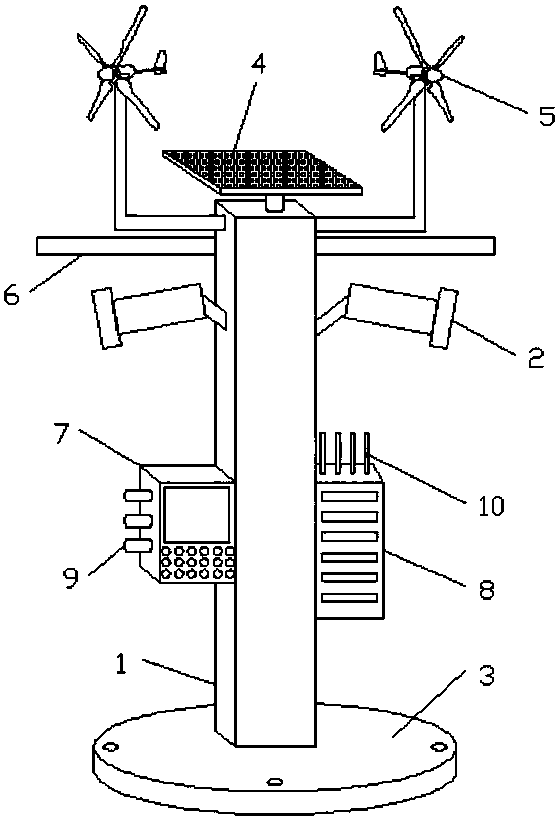
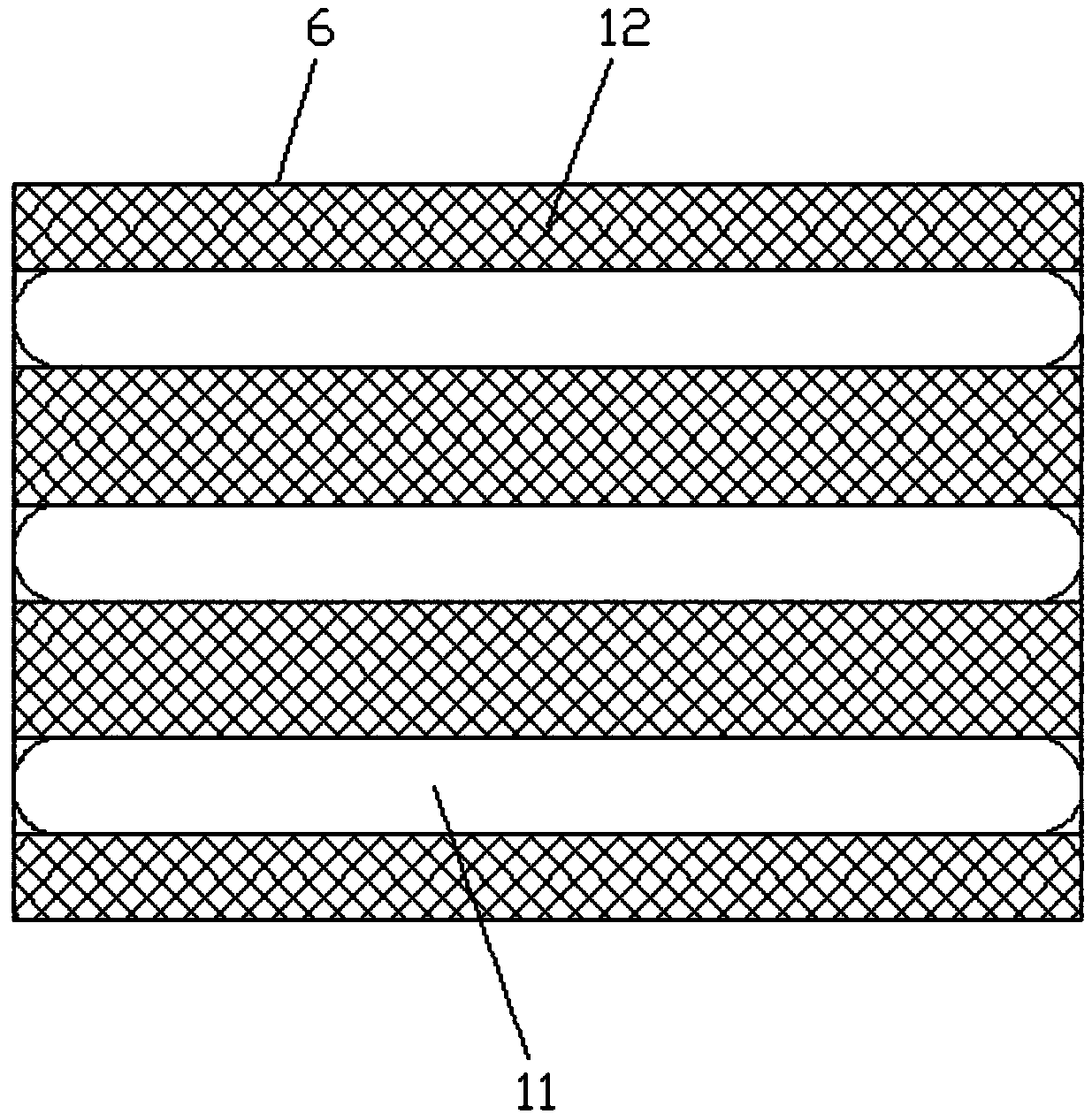
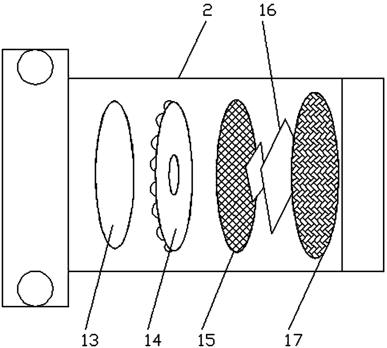
[0021] see Figure 1-3 , the embodiment of the present invention provides a technical solution: a safety monitoring device that can be remotely connected, including a monitoring device column 1, a camera 2, a base 3, a solar panel 4, a wind power generation device 5, a street lamp board 6, and a monitoring device 7 and an electric control box 8, a solar panel 4 is installed on the top of the monitoring device column 1, a wind power generation device 5 is insta...


PUM


Abstract

The invention discloses a safety monitoring device capable of being remotely connected. The safety monitoring device comprises a monitoring device vertical column, cameras, a base, a solar panel, windpower generation devices, street lamp panels, a supervising device and an electric control box; the solar panel is mounted at the top of the monitoring device vertical column, and the wind power generation devices are arranged on the two sides of the top of the monitoring device vertical column correspondingly; the street lamp panels are mounted at the bottoms of the wind power generation devices, and LED modulator tubes are distributed in the street lamp panels; metal net layers are connected to the bottoms of the street lamp panels through threads, and the cameras are arranged at the bottoms of the street lamp panels; and power panels, ultraviolet lamp panels, machine core plates, silicone pads and aluminum plate radiators are distributed in the cameras, and the supervising device is arranged on the left part of the middle of the monitoring device vertical column. According to the safety monitoring device capable of being remotely connected, energy conservation and environmental friendliness are achieved, the supervising device can be effectively utilized to conduct remote connecting control, the effect of high-definition monitoring is achieved, and mosquitoes are electrically shocked effectively to be prevented from entering the LED modulator tubes.

Description

technical field [0001] The invention relates to the technical field of monitoring devices, in particular to a remote-connectable safety monitoring device. Background technique [0002] The monitoring system is one of the most widely used systems in the security system. The most suitable construction site monitoring system on the market is a handheld video communication device, and video monitoring is now the mainstream. From the earliest analog monitoring to the fiery digital monitoring in the past few years, and now the network video monitoring is in the ascendant, earth-shaking changes have taken place. Now that IP technology is gradually unifying the world, it is necessary for us to re-understand the development history of video surveillance systems. From a technical point of view, the development of video surveillance systems is divided into the first generation of analog video surveillance systems (CCTV), the second generation of digital video surveillance systems (DVR...

Claims


Application Information

Patent Timeline
IPC IPC(8): F21S9/03F21S9/04F21V21/10F21V33/00F21V21/02F21V23/00F21V29/89F21V29/70F21V23/04F21V17/10F21V29/83F21Y115/10F21W131/103
CPCF21S9/035F21S9/043F21V17/101F21V21/02F21V21/10F21V23/003F21V23/0442F21V29/70F21V29/83F21V29/89F21V33/0052F21W2131/103F21Y2115/10Y02B20/72
Inventor 杨杰
Owner 扬州嘉杰物联科技有限公司
Learn More