A Distributed Thermal Pipeline Leakage Monitoring System

A thermal pipeline and monitoring system technology, applied in heating systems, heating methods, heat measurement, etc., can solve problems such as complex system structure, high operation and maintenance costs

Active Publication Date: 2020-10-20
BEIJING INST OF AEROSPACE CONTROL DEVICES
View PDF6 Cites 2 Cited by
  • Summary
  • Abstract
  • Description
  • Claims
  • Application Information

AI Technical Summary

Problems solved by technology

There are many technical means for temperature sensing and monitoring, but since thermal pipelines are transported over long distances, when using infrared thermal imaging technology and ordinary point temperature sensors to cover the entire pipeline network and monitor the temperature in real time, the system structure is complex and the operation and maintenance costs are relatively high. high

Method used


Image

  • A Distributed Thermal Pipeline Leakage Monitoring System
  • A Distributed Thermal Pipeline Leakage Monitoring System
  • A Distributed Thermal Pipeline Leakage Monitoring System

Examples


Embodiment Construction

[0044] The present invention will be further elaborated below in conjunction with the accompanying drawings.

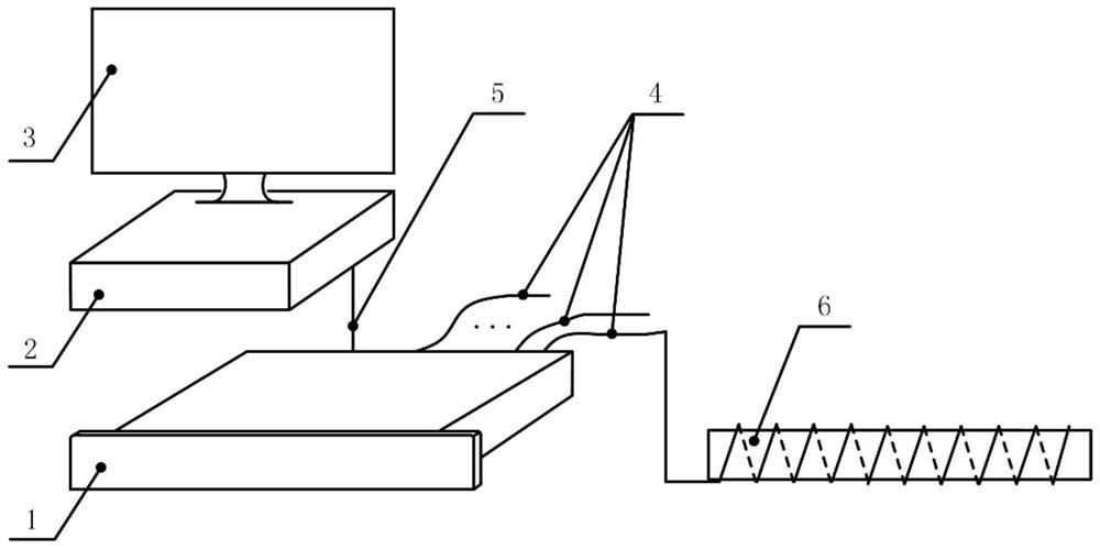
[0045] Such as figure 1 As shown, the present invention provides a distributed thermal pipeline leakage monitoring system, which includes an optical fiber temperature measurement host 1 , an industrial computer 2 , a display 3 , a temperature measurement optical cable 4 and a network cable 5 . in:

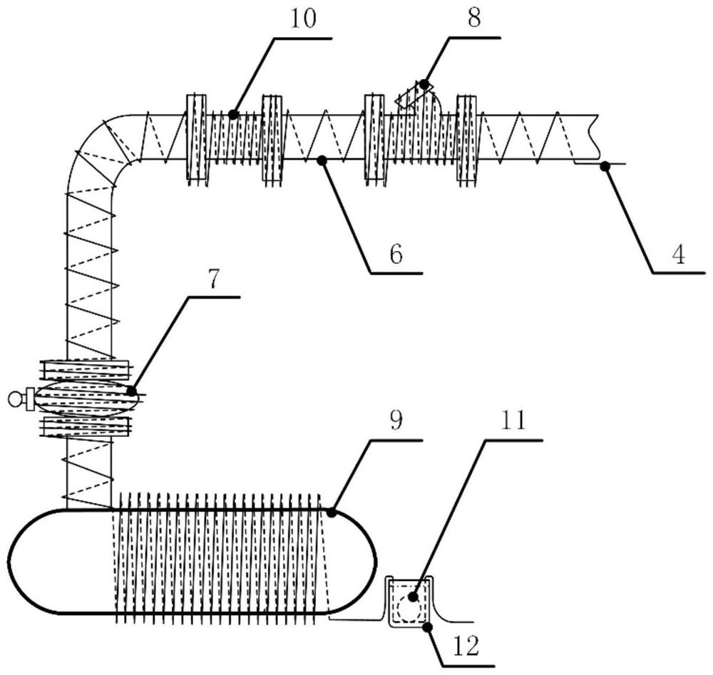
[0046] The optical fiber temperature measurement host 1 includes N temperature measurement channels, and each temperature measurement channel is connected to a temperature measurement optical cable 4. The temperature measurement optical cable 4 is laid along the entire pipeline with the thermal pipeline 6 as the carrier. Send pulsed light signals, collect the scattered light sent back from the temperature measuring optical cable 4 in real time, obtain the temperature and temperature change rate numerical curves of the entire line on the thermal pipeline 6 according to the...


PUM

PropertyMeasurementUnit
lengthaaaaaaaaaa

Abstract

The invention provides a distributed thermal pipeline leakage monitoring system. The system includes an optical fiber temperature measurement host, an industrial computer, and a temperature measurement optical cable, wherein: the optical fiber temperature measurement host includes N temperature measurement channels, and each temperature measurement channel is connected to A temperature measurement optical cable, the temperature measurement optical cable is laid along the whole pipeline with the thermal pipeline as the carrier, the temperature measurement channel sends pulsed light signals to the temperature measurement optical cable, and the scattered light sent back from the temperature measurement optical cable is collected in real time, according to the refractive index of the temperature measurement optical cable And the scattered light intensity, get the temperature and temperature change rate numerical curve of the whole line on the thermal pipeline, and determine the average temperature and maximum temperature change rate of the required monitoring position through the length of the optical cable laid on different monitoring positions from the optical fiber temperature measurement host , and determine whether each thermal pipeline is in a leaking state according to the set temperature change rate threshold.

Description

technical field [0001] The invention belongs to the technical field of on-line monitoring and measurement of thermal systems, and in particular relates to a distributed thermal pipeline leakage monitoring system. Background technique [0002] The thermal pipeline is the basic component of the heating system of the city or the park, and it is the circulation path for the heating medium to be transported to the thermal inlet of the building. In order to save the occupied area, at present, the construction method of laying the thermal pipeline is basically buried. However, the underground soil contains various substances such as air, water, salt, acid and alkali, and its complex environment is easy to damage the thermal pipeline, especially the pipeline. The valves, filters, water separators, water collectors and pipeline connections in the pipeline are corroded, resulting in pipeline leakage, causing serious waste of energy, shortening pipeline life and other problems, and may...

Claims


Application Information

Patent Timeline
Patent Type & Authority Patents(China)
IPC IPC(8): F24D19/10G01K11/32G01M3/00
CPCF24D19/1009G01K11/32G01M3/002F24D2220/042
Inventor 李俊一杜瑞李娜朱晓非杨潇君张海岩罗辉
Owner BEIJING INST OF AEROSPACE CONTROL DEVICES
Why Eureka
Try Eureka