Supercharge Your Innovation With Domain-Expert AI Agents!

Catalyst kiln waste heat recovery device

A waste heat recovery device and catalyst technology, which is applied in the direction of cleaning heat transfer devices, furnaces, heat exchangers, etc., can solve the problems of energy waste and flue gas waste heat not being used, so as to reduce energy consumption, prevent the cleaning effect from weakening, The effect of preventing the decrease in efficiency

Pending Publication Date: 2019-03-08
ZHEJIANG TUNA ENVIRONMENTAL SCI & TECH
View PDF0 Cites 0 Cited by
  • Summary
  • Abstract
  • Description
  • Claims
  • Application Information

AI Technical Summary

Problems solved by technology

[0004] The above existing technical solutions have the following defects: there is still a large amount of waste heat in the flue gas that has not been utilized, resulting in a waste of energy

Method used


Image

  • Catalyst kiln waste heat recovery device
  • Catalyst kiln waste heat recovery device
  • Catalyst kiln waste heat recovery device

Examples


Embodiment Construction

[0040] The present invention will be described in further detail below in conjunction with the accompanying drawings.

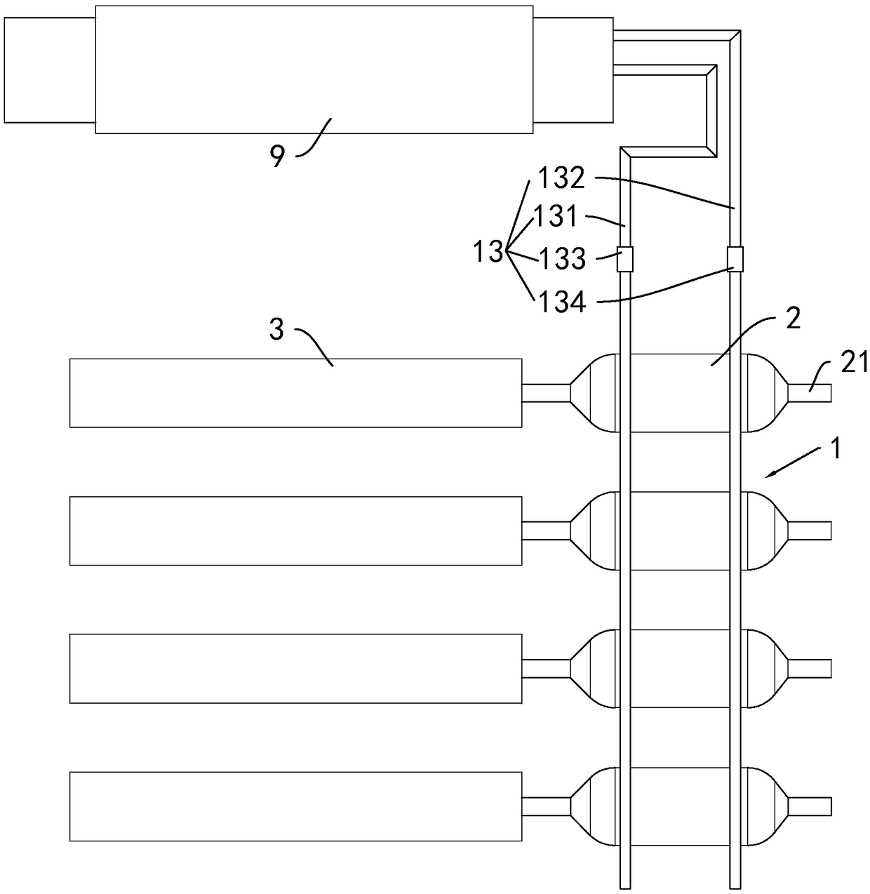
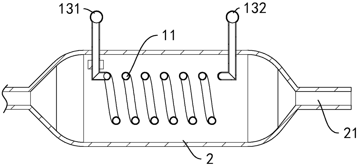
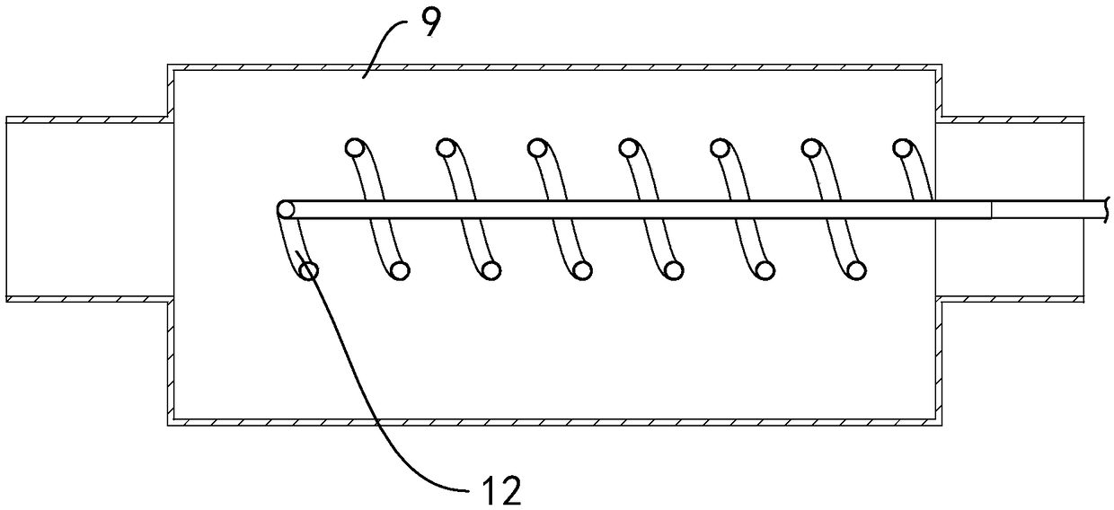
[0041] A catalyst kiln 3 waste heat recovery device, such as figure 1 As shown, it includes a heat exchange structure 1 and a heating chamber 2 . There are four heating chambers 2 and they are cylindrical in shape. The axes of the four heating chambers 2 are arranged horizontally. One end of each heating chamber 2 communicates with a kiln 3 through a smoke exhaust pipe, and the other end of each heating chamber 2 is fixed. An exhaust pipe 21 is connected. The heat exchange structure 1 includes a first heat exchange tube 11 (see figure 2 ), the second heat exchange tube 12 (see image 3 ) and the loop structure 13. Four of the first heat exchange tubes 11 are respectively fixedly connected in the four heating chambers 2 , and the first heat exchange tubes 11 are in a spiral shape and arranged coaxially with the heating chambers 2 . The second heat exchan...


PUM


Abstract

The invention discloses a catalyst kiln waste heat recovery device and belongs to the field of energy recovery. According to the key points of the technical scheme, the catalyst kiln waste heat recovery device comprises a heat exchange structure, an ash clearing device and a heating chamber which communicates with a kiln and communicates with a smoke exhausting pipeline. The heat exchange structure comprises a first heat exchange pipe fixedly connected into the heating chamber, a second heat exchange pipe fixedly connected into a tunnel kiln, and a circulating structure. The circulating structure enables the first heat exchange pipe and the second heat exchange pipe to communicate. The ash clearing device is arranged on the first heat exchange pipe. The catalyst kiln waste heat recovery device has the effect of saving energy.

Description

technical field [0001] The invention relates to the technical field of energy recovery, more specifically, it relates to a catalyst kiln waste heat recovery device. Background technique [0002] Realizing the goal of energy saving, emission reduction and improving energy utilization mainly depends on the industrial field. In China, which is in the middle and late stages of industrialization, industry is the main energy-consuming field and the main source of pollutant emissions. Energy consumption in my country's industrial sector accounts for about 70% of the country's total energy consumption, and the average unit energy consumption of major industrial products is about 30% higher than the international advanced level. In addition to factors such as relatively backward production technology and unreasonable industrial structure, the low utilization rate of industrial waste heat and insufficient comprehensive utilization of energy (energy) are important reasons for high ene...

Claims


Application Information

Patent Timeline
IPC IPC(8): F27D17/00F28D7/02F28D21/00F28G3/04F28G15/04F28G15/00
CPCF27D17/004F28D7/024F28D21/0003F28G3/04F28G15/003F28G15/04Y02P10/25
Inventor 赵博蔡学军宣学伟陈小利蒋成军田伟丰
Owner ZHEJIANG TUNA ENVIRONMENTAL SCI & TECH
Features
  • R&D
  • Intellectual Property
  • Life Sciences
  • Materials
  • Tech Scout
  • Unparalleled Data Quality
  • Higher Quality Content
  • 60% Fewer Hallucinations
Learn More