
Optical position detection device and method

An optical position detection and light source technology, which is applied in the direction of optical devices, measuring devices, instruments, etc., can solve the problems of deviation from the detection position and large irradiation area, and achieve high detection accuracy, low cost, and clear and sharp edge contours

Pending Publication Date: 2019-03-08
苏州亿拓光电科技有限公司
View PDF2 Cites 2 Cited by
  • Summary
  • Abstract
  • Description
  • Claims
  • Application Information

AI Technical Summary

Problems solved by technology

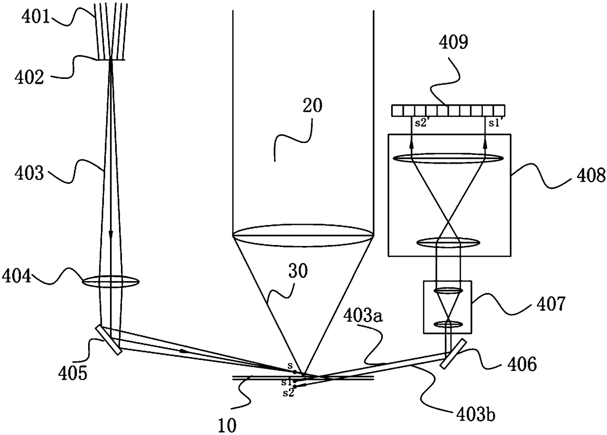
[0006] 1. The irradiation area is large, which is easily affected by dust and the fluctuation of the detection surface;
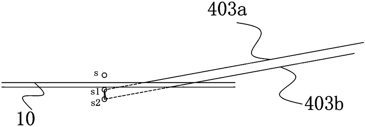
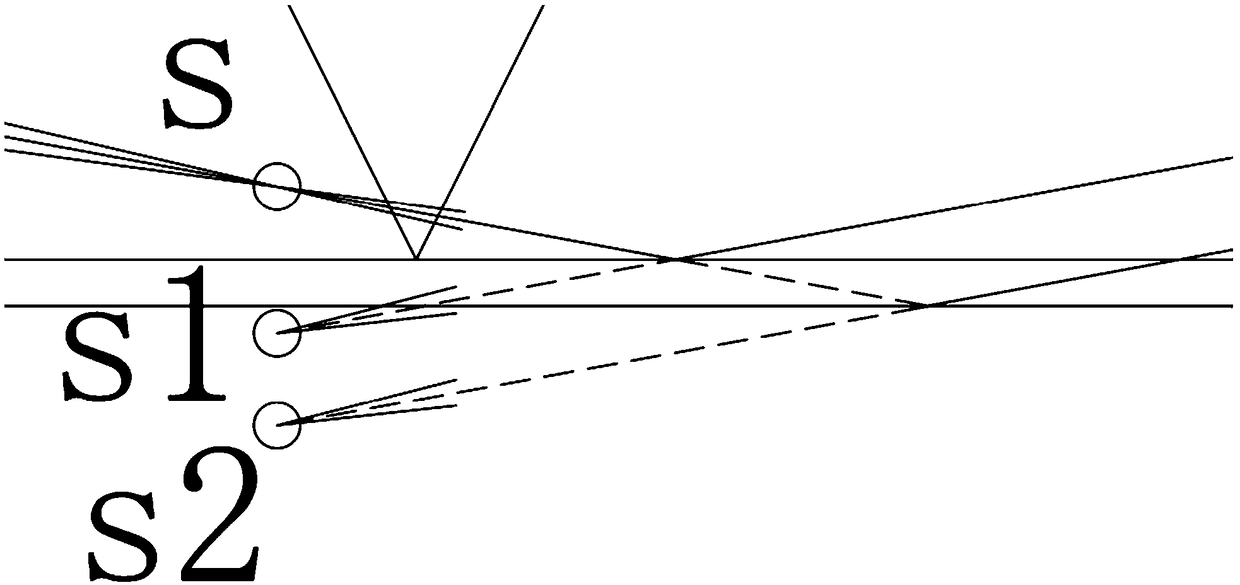
[0007] 2. When the position of the workpiece surface changes up and down, the area irradiated by the detection light will shift left and right, which may deviate from the predetermined detection position

Method used


Image

  • Optical position detection device and method
  • Optical position detection device and method
  • Optical position detection device and method

Examples


Embodiment Construction

[0036] The technical solutions in the embodiments of the present invention will be described in detail and completely below in conjunction with the accompanying drawings in the embodiments of the present invention. Obviously, the described embodiments are only some, not all, embodiments of the present invention. Based on the embodiments of the present invention, all other embodiments obtained by persons of ordinary skill in the art without making creative efforts belong to the protection scope of the present invention.

[0037] In the description of the present invention, it should be noted that the terms "center", "upper", "lower", "left", "right", "vertical", "horizontal", "inner", "outer" etc. The indicated orientation or positional relationship is based on the orientation or positional relationship shown in the drawings, and is only for the convenience of describing the present invention and simplifying the description, rather than indicating or implying that the referred d...


PUM

PropertyMeasurementUnit
Magnificationaaaaaaaaaa

Abstract

The invention discloses an optical position detection device. The device comprises a detection light source as well as a diaphragm, a projection lens group, an imaging magnifier group and a detector arranged along the imaging optical path of the detection light source successively, the detection light source is a point or line light source, the projection lens group input a light beam from the diaphragm to the to-be-measured surface of a workpiece in certain inclination angle, and the imaging magnifier group carriers out secondary amplifying imaging on a reflection light beam of the to-be-measured surface and then input the light beam to the detector. The invention also discloses an optical position detection method. According to the detection device and method, an independent imaging optical path is used, the edge contour is clearer, the detection precision is higher, the inclined input manner with different angles is used, the spatial position occupied by other optical paths can be avoided, the device is simple and reliable, the cost is low, position change in the surface of the workpiece can be amplified by 30-160 times, and submicron order position detection can be realized.

Description

technical field [0001] The present application relates to the technical field of optical processing, in particular to an optical position detection device and method. Background technique [0002] The optical position detection method has the advantages of non-contact, high precision and fast response, and is widely used in the fields of positioning control and product shape detection. [0003] There are many existing optical position detection methods: confocal method (also known as confocal method, which is more common in laser confocal microscopes), triangulation method (which is widely used in current commercial laser displacement sensors), interferometry ( Such as dual-frequency laser interferometer), astigmatism method (the servo focusing of the optical drive adopts the modified method, and is also used in precision optical processing, such as patent 201010170978.4) and so on. [0004] In special cases, the above methods are difficult to meet the needs. For example: ...

Claims


Application Information

Patent Timeline
IPC IPC(8): G01B11/00G01B9/00
CPCG01B9/00G01B11/00
Inventor 胡进陈铭勇
Owner 苏州亿拓光电科技有限公司
Learn More