Discharging circuit fault detection device and method
A technology of fault detection and discharge circuit, which is applied in the direction of electronic circuit testing, measuring devices, measuring electricity, etc., can solve problems such as alarming, damage to drive hardware, and high bus voltage of the drive, so as to reduce costs, improve reliability, and ensure no damage. Effect
- Summary
- Abstract
- Description
- Claims
- Application Information
AI Technical Summary
Problems solved by technology
Method used
Image

Examples
Embodiment 1
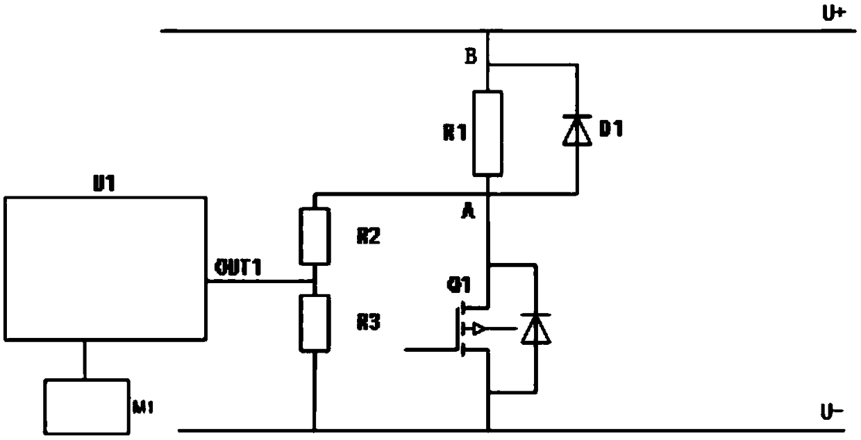
[0027] Discharge circuit fault detection device such as figure 1 As shown, the two ends of the discharge resistor R1 are A terminal and B terminal respectively. The power device Q1 is an IGBT or MOSFET with a parasitic diode. The discharge resistor R1 is connected in series with the power device Q1 and then connected in parallel with the positive and negative busbars U+ and U-. Diode D1 is connected in parallel with both ends of discharge resistor R1. The voltage dividing resistor R2 and R3 are connected in parallel with the terminal A of the discharge resistor R1 and the negative bus U- after being connected in series. OUT1 is an output point between the voltage dividing resistors R2 and R3, OUT1 is connected to the input terminal of U1, and the output terminal of U1 is connected to the control unit M1.
[0028] The discharge resistor R1 is mainly used to release excess energy on the bus. The main function of diode D1 is freewheeling. The main function of the power device ...
Embodiment 2
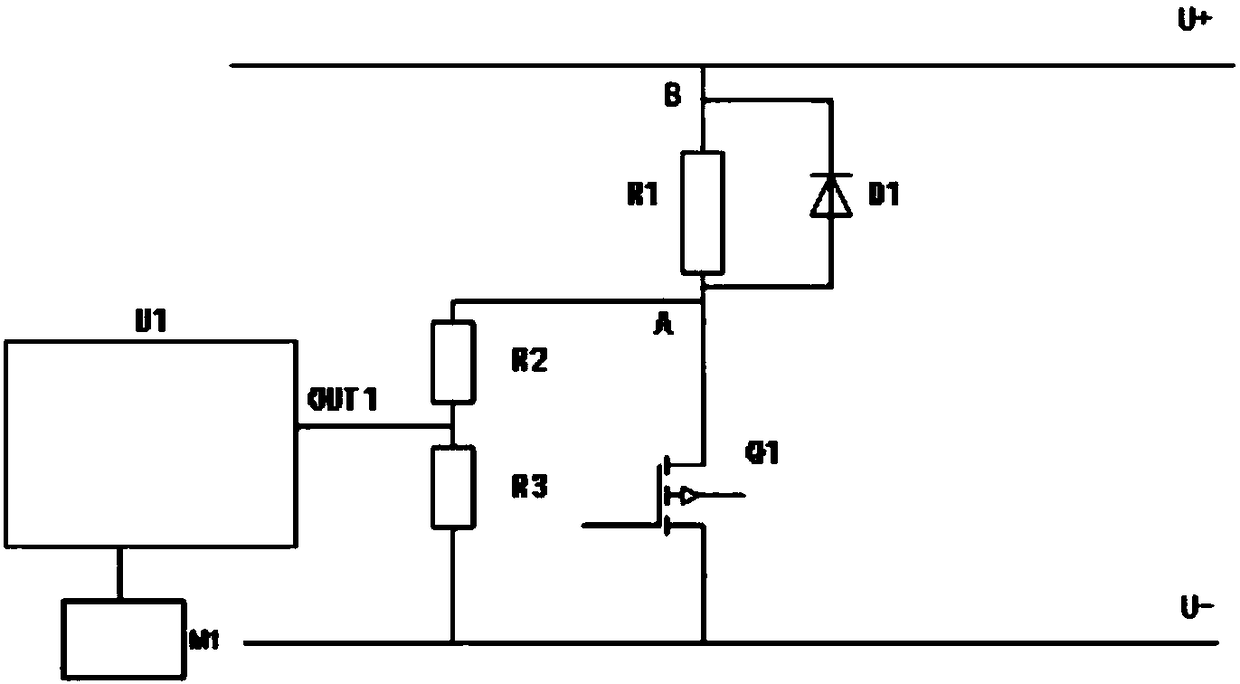
[0034]Discharge circuit fault detection device such as figure 2 As shown, it is basically the same as the discharge circuit fault detection device in Embodiment 1, except that in this embodiment, the power device Q1 is an IGBT or MOSFET without a parasitic diode.
[0035] In this embodiment, the fault judging device U1 according to the voltage value V OUT1 To determine whether the power device Q1 has a short circuit or an open circuit fault, the specific determination method is the same as that in Embodiment 1.
Embodiment 3
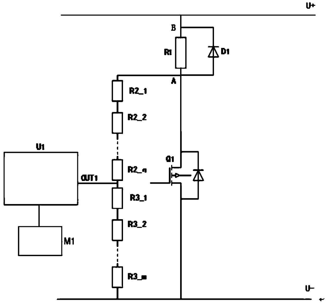
[0037] Discharge circuit fault detection device such as image 3 As shown, it is basically the same as the discharge circuit fault detection device in Embodiment 1, the difference is that in this embodiment, the voltage dividing resistor R2 is composed of n sub-resistors, that is, R2_1, R2_2, ..., R2_n, n≥ 2. The voltage dividing resistor R3 is composed of m sub-resistors, that is, R3_1, R3_2, . . . , R3_m, where m≥2.
[0038] In this embodiment, the bus voltage is divided by resistors R2_1, R2_2, ..., R2_n, R3_1, R3_2, ..., R3_m, and the fault judging device U1 obtains the required divided voltage value V through the output point OUT1 OUT1 . When Q1 is off, V OUT1 =(U + -U - )×(R3_1+R3_2+……+R3_m) / (R1+R2_1+R2_2+…+R2_n+R3_1+R3_2+…+R3_m); when Q1 is closed, Q1 is approximately a wire, and V OUT1 =V1, V1≥0 and a very small voltage value.
[0039] The fault judging device U1 according to the voltage value V OUT1 To judge whether the power device Q1 has a short circuit or op...
PUM
 Abstract
Description
Claims
Application Information
 - R&D
- Intellectual Property
- Life Sciences
- Materials
- Tech Scout
- Unparalleled Data Quality
- Higher Quality Content
- 60% Fewer Hallucinations
Browse by: Latest US Patents, China's latest patents, Technical Efficacy Thesaurus, Application Domain, Technology Topic, Popular Technical Reports.
© 2025 PatSnap. All rights reserved.Legal|Privacy policy|Modern Slavery Act Transparency Statement|Sitemap|About US| Contact US: help@patsnap.com