
Laser emission system

A laser emission system and laser reflection technology, applied in the laser field, can solve the problem of low laser frequency

Pending Publication Date: 2019-03-08
SUTENG INNOVATION TECH CO LTD
View PDF0 Cites 3 Cited by
  • Summary
  • Abstract
  • Description
  • Claims
  • Application Information

AI Technical Summary

Problems solved by technology

[0005] Based on this, it is necessary to provide a laser emitting system for the problem of low laser emission frequency of lidar

Method used


Image

  • Laser emission system
  • Laser emission system
  • Laser emission system

Examples


Embodiment Construction

[0042] As a distance measuring device, laser radar is more and more used in people's lives. Products using laser radar can be widely used in unmanned driving, drones, service robots, three-dimensional measurement and digital modeling and other fields, providing various conveniences for people's lives. The detection effect of lidar is related to the frequency of the laser emitting device. The higher the emission frequency, the better the detection effect. Usually, a laser light source is used to generate laser light, and the laser light is collimated through the collimation optical path to obtain the collimated laser light, which is to emit laser light. The emitted laser light generated by the above method is affected by the characteristics of the emitted light source itself, so the frequency of emitted laser light is relatively low. The laser emission system provided by this application aims to solve the above problems.

[0043] In order to make the purpose, technical soluti...


PUM


Abstract

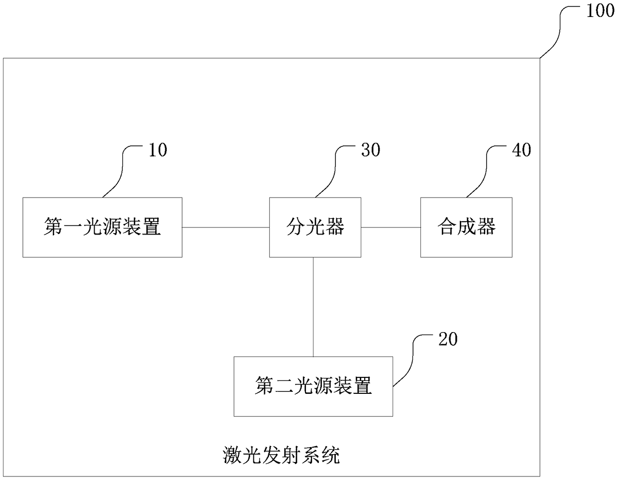
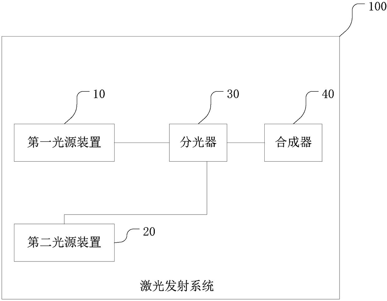
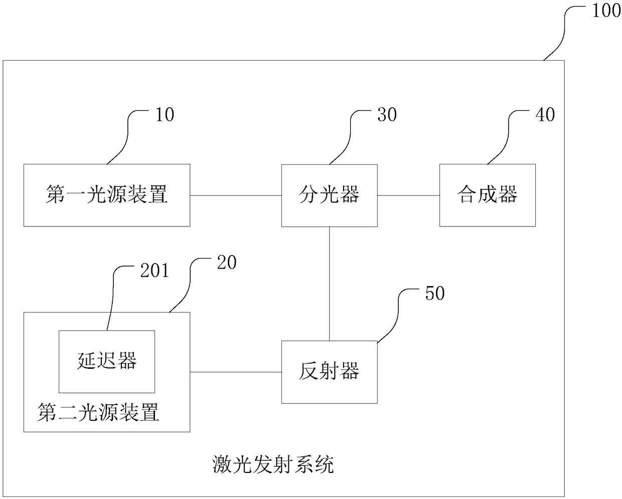
The invention relates to a laser emission system. The system comprises a first light source device, a second light source device, an optical splitter, and a synthesizer. The first light source deviceand the second light source device are optically connected to the optical splitter. The optical splitter is optically connected to the synthesizer. The first light source device and the second light source device are used for emitting a polarized laser. The polarized laser comprises a P state laser and an S state laser. The optical splitter is used to transmit the P state laser in the polarized laser and reflect the S state laser, or to transmit the S state laser in the polarized laser and reflect the P state laser. The synthesizer is used to synthesize the two paths of polarized lasers outputby the optical splitter into one path of laser. By using the laser emission system, the polarized lasers emitted by the first light source device and the second light source device pass through the optical splitter and the synthesizer, and then the two paths of lasers are combined into one path so that the frequency of the laser emitted by the laser emission system is doubled; and the frequency of the laser emitted by the laser emission system is increased and then the performance of the laser emitted by the laser emission system is improved.

Description

technical field [0001] The invention relates to the technical field of lasers, in particular to a laser emitting system. Background technique [0002] As a distance measuring device, laser radar is more and more used in people's lives. Products using laser radar can be widely used in unmanned driving, drones, service robots, three-dimensional measurement and digital modeling and other fields, providing various conveniences for people's lives. [0003] The detection effect of lidar is related to the frequency of the laser emitting device. The higher the emission frequency, the better the detection effect. Usually, a laser light source is used to generate laser light, and the laser light is collimated through the collimation optical path to obtain the collimated laser light, which is to emit laser light. [0004] The emitted laser light generated by the above method is affected by the characteristics of the emitted light source itself, so the frequency of emitted laser light...

Claims


Application Information

Patent Timeline
Patent Type & Authority Applications(China)
IPC IPC(8): G02B27/28G02B27/30G02B5/30G01S7/481G01S17/02
CPCG02B27/283G02B27/286G02B27/30G01S7/4814G01S17/02G02B5/3083
Inventor 邱纯鑫刘乐天
Owner SUTENG INNOVATION TECH CO LTD
Learn More