
A heat dissipation device and method for an M.2 solid state disk of a server

A solid-state hard drive and cooling device technology, which is applied in the direction of instruments, electrical digital data processing, digital data processing components, etc., can solve the problems of reducing the height and space of the cooling device, achieve optimized cooling effect, reduce system power consumption, and increase wind speed Effect

Inactive Publication Date: 2019-03-08
ZHENGZHOU YUNHAI INFORMATION TECH CO LTD
View PDF0 Cites 0 Cited by
  • Summary
  • Abstract
  • Description
  • Claims
  • Application Information

AI Technical Summary

Problems solved by technology

[0008] In order to overcome the shortcomings of the above-mentioned prior art, the present invention provides a heat dissipation device and method for M.2 solid-state hard disks of servers. By setting up an independent heat dissipation device for M.2 solid-state hard disks, the wind enters from the bottom and the air exits from the side. The way of wind reduces the height space occupied by the cooling device, and avoids the top board card from affecting the air intake of the fan when the upper part enters the air. The air intake is greatly improved, and the turbofan under the same power can provide a greater air outlet speed. and air volume, thereby reducing system power consumption, avoiding problems such as increased power consumption and increased noise caused by system fan speed up, reducing user operating costs, and greatly improving heat dissipation

Method used


Image

  • A heat dissipation device and method for an M.2 solid state disk of a server
  • A heat dissipation device and method for an M.2 solid state disk of a server
  • A heat dissipation device and method for an M.2 solid state disk of a server

Examples


Embodiment Construction

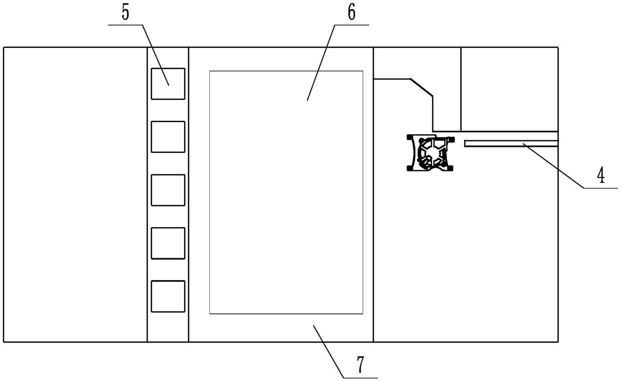
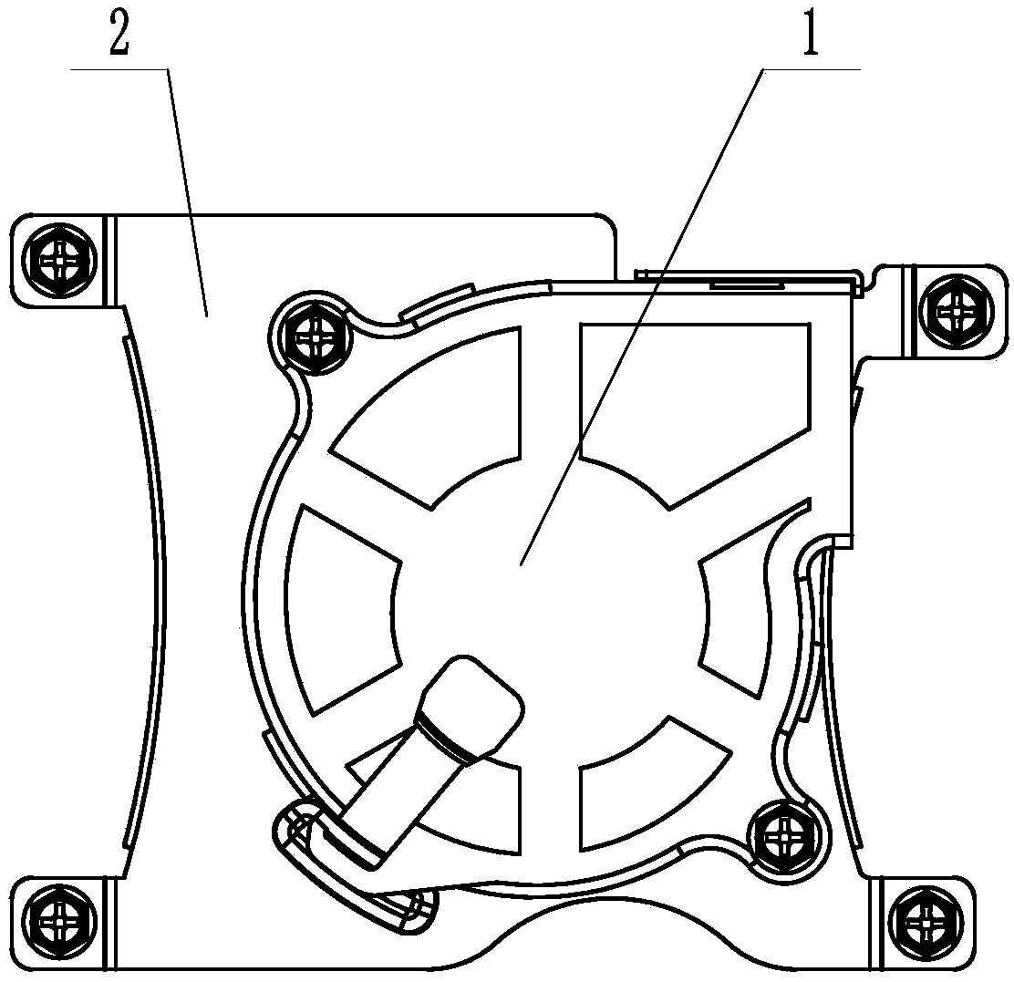
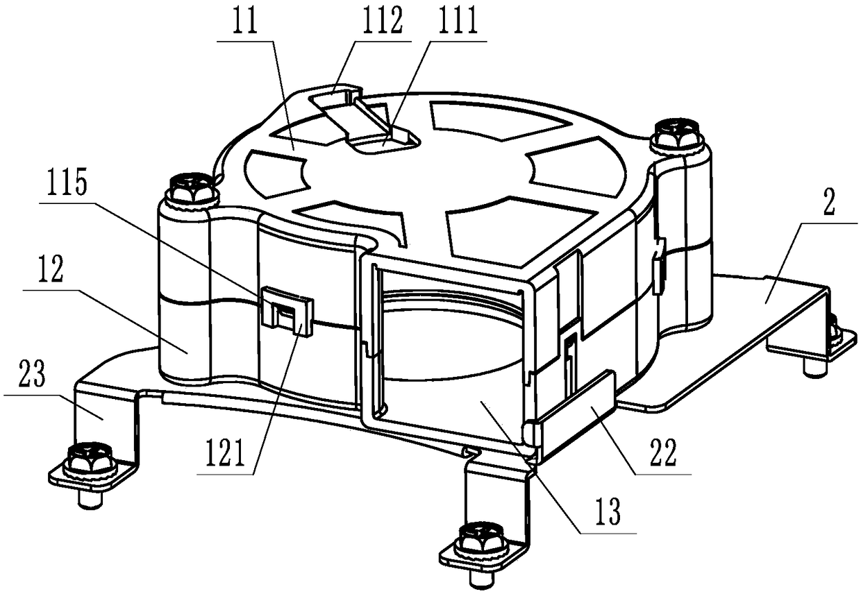
[0036] In order to better understand the present invention, the implementation manner of the present invention will be explained in detail below in conjunction with the accompanying drawings.

[0037] Such as Figure 1-3 As shown, a heat dissipation device for M.2 solid-state hard drives in servers includes a fan housing 1, a vortex fan 3 is provided inside the fan housing 1, an air outlet 13 is provided on the side of the fan housing 1, and an air outlet 13 is provided at the bottom of the fan housing 1. Housing air inlet 14, the bottom of the fan housing 1 is connected to the housing base 2, the housing base 2 is provided with a base air inlet 24 matching the housing air inlet 14, and the housing base 2 is installed on the main board On the side of 7 close to the M.2 solid state drive 4, the air outlet 13 faces the M.2 solid state drive 4, and there is a gap between the air inlet 24 of the base and the main board 7;

[0038] By setting the turbofan 3, the bottom air intake ...


PUM


Abstract

The invention discloses a heat dissipation device and method for an M.2 solid state disk of a server. An independent heat dissipation device is arranged on one side of an M.2 solid-state hard disk; the system independently controls the heat dissipation device according to the temperature of the M.2 solid state disk; an air outlet of the heat dissipation device faces the M.2 solid state disk, and an air inlet of the heat dissipation device faces the main board. The heat dissipation device comprises a fan shell, a vortex fan is arranged in the fan shell; an air outlet is formed in the side faceof the fan shell, a shell air inlet is formed in the bottom of the shell, a base air inlet matched with the shell air inlet is formed in the shell base, and the shell base is installed on the side, close to the M.2 solid state disk, of the main board. According to the present invention, the bottom air inlet and the side face air outlet mode are adopted, so that the height space occupied by the heat dissipation device is reduced, the turbofan under the same power can provide larger air outlet speed and larger air outlet amount, the system power consumption is reduced, the noise is reduced, andmeanwhile the heat dissipation effect is greatly improved.

Description

technical field [0001] The invention relates to the technical field of server heat dissipation, in particular to a heat dissipation device and method for server M.2 solid-state hard disks. Background technique [0002] Since the launch of NVMe M.2 solid-state drives in April 2015, M.2 solid-state drives have been widely used in servers due to their excellent operating performance; although M.2 solid-state drives are small in size, their power consumption density and However, the heat is relatively high. If the heat dissipation of the M.2 solid-state hard drive is not timely, the performance will drop or even burn out. Therefore, the M.2 solid-state hard drive needs a high-speed airflow to ensure its heat dissipation requirements. [0003] In the prior art, since key components such as CPU and memory need to give priority to heat dissipation, M.2 solid-state drives are often arranged behind the motherboard, and there is a long distance between them and the system cooling fan,...

Claims


Application Information

Patent Timeline
Patent Type & Authority Applications(China)
IPC IPC(8): G06F1/20
CPCG06F1/20Y02D10/00
Inventor 于光义
Owner ZHENGZHOU YUNHAI INFORMATION TECH CO LTD
Learn More