
High-speed impeller

An impeller, high-speed technology used in parts of pumping devices for elastic fluids, non-variable displacement pumps, machines/engines, etc., to reduce airflow resistance

Pending Publication Date: 2020-06-30
CINDERSON TECH (SUZHOU) CO LTD
View PDF0 Cites 0 Cited by
  • Summary
  • Abstract
  • Description
  • Claims
  • Application Information

AI Technical Summary

Problems solved by technology

[0003] The problem to be solved by the present invention is to provide a high-speed impeller, which can relieve pressure and reduce speed when the air inlet is blocked, and protect the impeller.

Method used


Image

  • High-speed impeller
  • High-speed impeller
  • High-speed impeller

Examples


Embodiment Construction

[0039] Below in conjunction with specific embodiment, content of the present invention is described in further detail:

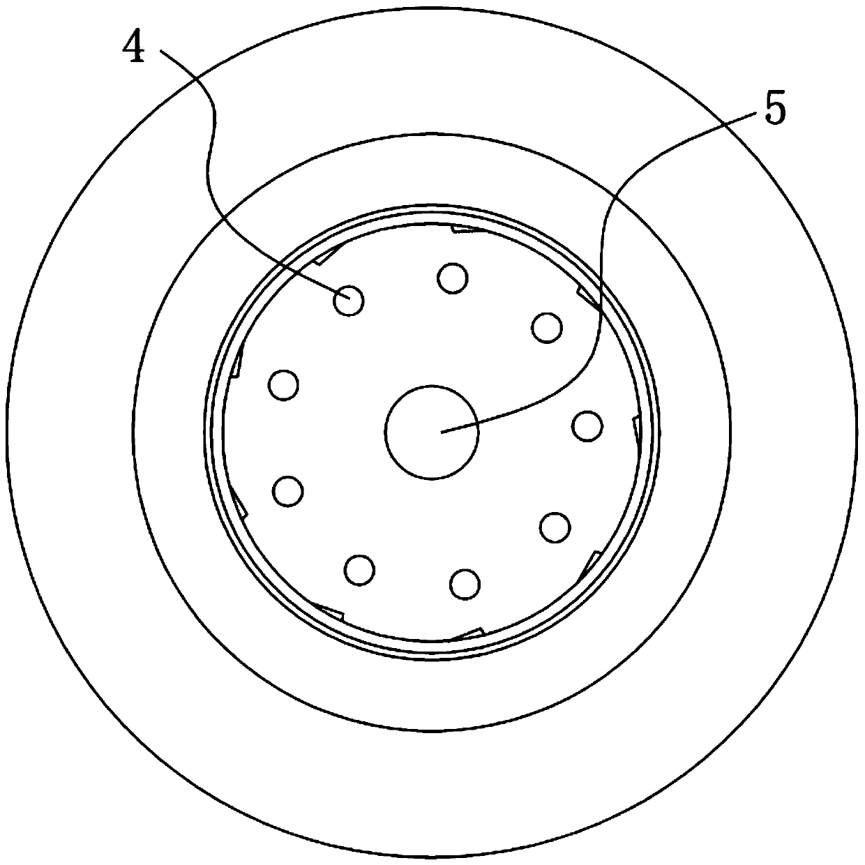
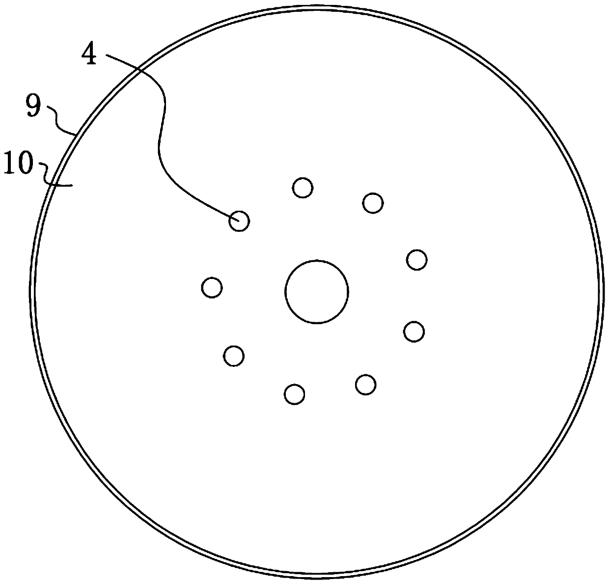
[0040] In order to achieve the purpose of the present invention, a high-speed impeller includes: an impeller body, including an upper disk 1 and a lower disk 2 coaxially arranged, and the upper disk 1 and the lower disk 2 are connected by several blades 3 in an annular array , the upper plate 1 is equipped with an air inlet 6, the lower plate 2 is fixed to the rotating motor; the pressure relief hole 4 runs through a pair of parallel surfaces of the lower plate 2, and several pressure relief holes 4 are formed around the axis of the lower plate 2 itself Annular array; skirts, including the upper skirt 9 respectively located on the edge of the upper disk part 1 and extending radially, and the lower skirt 10 extending radially along the edge of the lower disk part 2, and the blades 3 are located between the pressure relief hole 4 and the skirt between sides. ...


PUM


Abstract

The invention discloses a high-speed impeller. The high-speed impeller comprises an impeller body, a plurality of pressure relief holes and skirt edges, the impeller body comprises an upper disc pieceand a lower disc piece which are coaxially arranged, the upper disc piece and the lower disc piece are connected through a plurality of blades in an annular array, an air inlet is formed in the upperdisc piece, the lower disc piece is fixed to a rotating motor; the pressure relief holes penetrate through a pair of parallel faces of the lower disc piece, the plurality of pressure relief holes areannularly arrayed around the axis of the lower disc piece; and the skirt edges comprise an upper skirt edge which is located on the edge of the upper disc piece and extends in the radial direction and a lower skirt edge which is located on the edge of the lower disc piece and extends in the radial direction, and the blades are located between the pressure relief holes and the skirt edges. According to the high-speed impeller, press relief and speed reduction can be realized under the condition that the air inlet is blocked, the impeller is protected; and the two skirt edges increase the structural strength of joints of the blades and the upper disc piece and the lower disc piece under the condition that the running wind resistance of the impeller is not increased, and the the structural strength of the whole impeller at a high rotating speed is improved.

Description

technical field [0001] The invention relates to the field of impellers, in particular to a high-speed impeller. Background technique [0002] Now brushless motors for vacuum cleaners are becoming more and more popular in the market because of their small size and high suction power. The core part of this motor is its impeller. However, as the speed increases, the structure of the current conventional impeller can no longer meet the demand. The existing impeller is composed of three parts, the upper piece, the middle piece, and the lower piece. The holes on the blade and the lower blade are fixed by riveting, and at higher and higher speeds, it will cause fatigue of the material, which may eventually lead to disintegration of the impeller. Contents of the invention [0003] The problem to be solved by the present invention is to provide a high-speed impeller, which can release pressure and reduce speed when the air inlet is blocked, so as to protect the impeller. The two ...

Claims


Application Information

Patent Timeline
Patent Type & Authority Applications(China)
IPC IPC(8): F04D29/28F04D29/30F04D29/42
CPCF04D29/281F04D29/30F04D29/4206
Inventor 朱云舫
Owner CINDERSON TECH (SUZHOU) CO LTD
Learn More