C-shaped cable clamp

A wire clip and clip seat technology, applied in the direction of multi-conductor connectors, contact parts, electrical components, etc., can solve the problems of irregular shape, easy falling of parts, etc., to increase the friction coefficient, good electrical conductivity, and prevent slipping. Effect

Pending Publication Date: 2019-03-08
YONGGU GRP
View PDF0 Cites 2 Cited by
  • Summary
  • Abstract
  • Description
  • Claims
  • Application Information

AI Technical Summary

Problems solved by technology

[0004] Therefore, in order to overcome the problems of the irregular shape and the easy loss of parts of the C-shaped wire clamps that are fastened by bolts in the prior art, a C-shaped wire clamp that can be fastened without bolts is provided.

Method used


Image

  • C-shaped cable clamp
  • C-shaped cable clamp
  • C-shaped cable clamp

Examples


Embodiment Construction

[0028] The technical solutions of the present invention will be clearly and completely described below in conjunction with the accompanying drawings. Apparently, the described embodiments are some of the embodiments of the present invention, but not all of them. Based on the embodiments of the present invention, all other embodiments obtained by persons of ordinary skill in the art without making creative efforts belong to the protection scope of the present invention.

[0029] In the description of the present invention, it should be noted that the terms "center", "upper", "lower", "left", "right", "vertical", "horizontal", "inner", "outer" etc. The indicated orientation or positional relationship is based on the orientation or positional relationship shown in the drawings, and is only for the convenience of describing the present invention and simplifying the description, rather than indicating or implying that the referred device or element must have a specific orientation, ...


PUM


Abstract

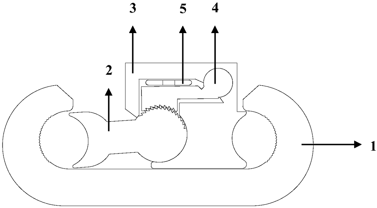
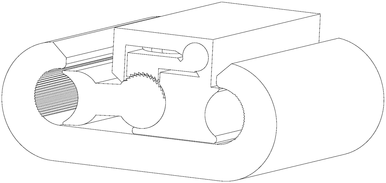
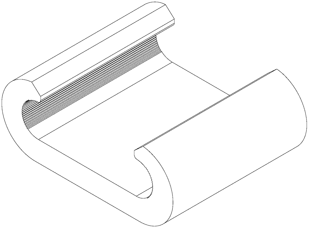
The invention provides a C-shaped cable clamp. The C-shaped cable clamp comprises a C-shaped clamping base, a movable block assembly, a check limiting part and an elastic part; the C-shaped clamping base is a column structure which is made of a conductive material and has a C-shaped cross section; the movable block assembly comprises an inner movable block and an outer movable block which are hinged with each other, the inner movable block is provided with a hinged end, the outer movable block is provided with a hinged groove corresponding to the hinged end of the inner movable block, a non-hinged end of the inner movable block and a non-hinged end of the outer movable block can cooperate with the two ends of the C-shaped clamping base to clamp a cable, and the outer movable block is further provided with a reserved space communicated with the hinge groove; the check limiting part is arranged in the reserved space, the surface of the check limiting part and the surface of the inner movable block are provided with check structures cooperating with each other, and the check structures are used for enabling the inner movable block and the outer movable block to be only capable of moving in the direction capable of enabling an included angle formed by the inner movable block and the outer movable block to be enlarged; and the elastic part is arranged between the outer movable blockand the check limiting part to apply support force towards the surface of the inner movable block to the check limiting part.

Description

technical field [0001] The invention relates to the technical field of cable installation, in particular to a C-shaped clamp. Background technique [0002] C-type clamp is a kind of electric power connection fittings. As a kind of conductor connection terminal (line joint) for continuous current, it requires a large (continuous) flow capacity. It is named after the shape of the English letter C. When the C-type clamp is used as the current connection of the wire, the crimping is tight and the connecting joint is integrated. After crimping, the sleeve is fully covered with the wire, the current conduction is evenly distributed, the resistance is small, only micro-ohm level, the temperature is low and the resistance is low. Large pulling force can reduce the failure rate by more than 80%. Make the line have stable and good contact performance, avoid maintenance, reduce maintenance costs, reduce energy consumption, and save energy. [0003] Most of the current old-fashioned C...

Claims


Application Information

Patent Timeline
Patent Type & Authority Applications(China)
IPC IPC(8): H01R11/03H01R13/15H01R13/639H01R13/629
CPCH01R11/03H01R13/15H01R13/629H01R13/639
Inventor 徐驰达郑革陈杰任永琼方伟
Owner YONGGU GRP
Why Eureka
Try Eureka