A Fault Current Limiting Method for Distributed Capacitor Configuration in DC System

A DC system, fault current limiting technology, applied in emergency protection circuit devices, electrical components and other directions, can solve the problems of large fault damage, reduction, rapid development of DC faults, etc., to reduce fault current level, reduce performance requirements, The effect of reducing the total capacity of the capacitor

Active Publication Date: 2019-12-27
TIANJIN UNIV
View PDF4 Cites 0 Cited by
  • Summary
  • Abstract
  • Description
  • Claims
  • Application Information

AI Technical Summary

Problems solved by technology

[0003] Aiming at the problems of fast development of DC faults in DC systems, great fault hazards, and difficult DC fault current interruption technology, the present invention proposes a fault current limiting method for distributed capacitor configuration in DC systems, and provides corresponding fault ride-through control and The strategy of restoring power supply after the fault is cleared can reduce the DC fault current level and enhance the fault ride-through capability of the network

Method used


Image

  • A Fault Current Limiting Method for Distributed Capacitor Configuration in DC System
  • A Fault Current Limiting Method for Distributed Capacitor Configuration in DC System
  • A Fault Current Limiting Method for Distributed Capacitor Configuration in DC System

Examples


Embodiment Construction

[0014] The present invention will be described below in conjunction with the accompanying drawings and embodiments.

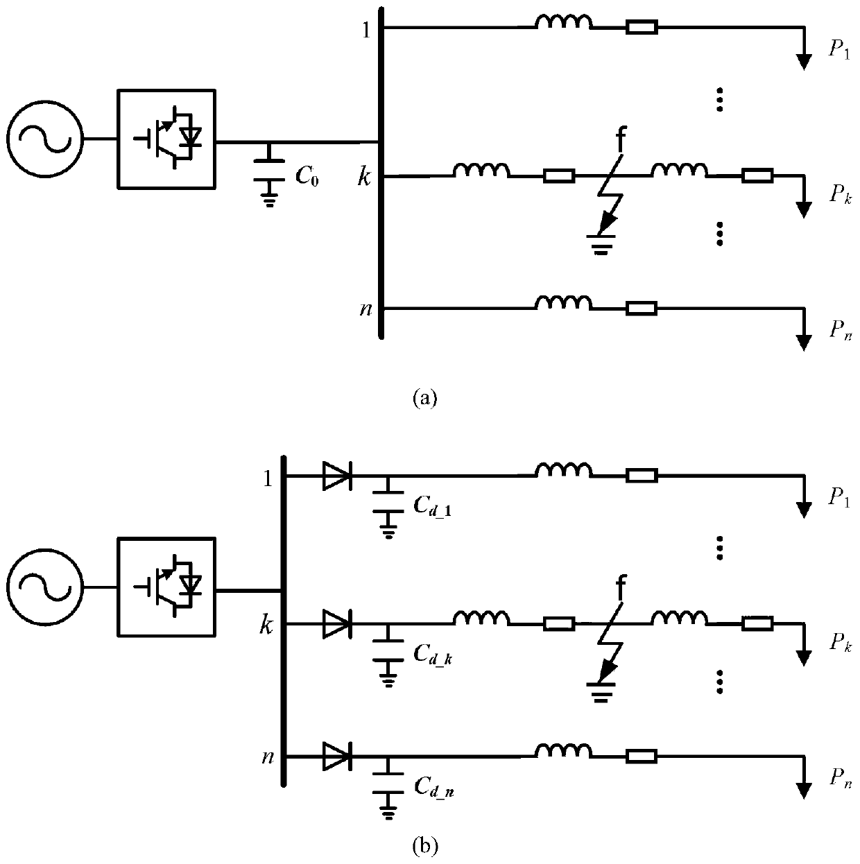
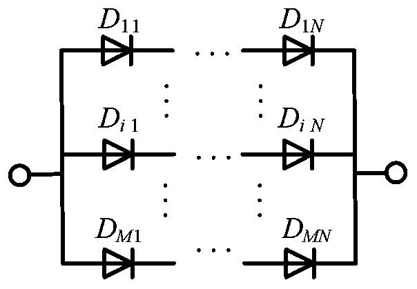
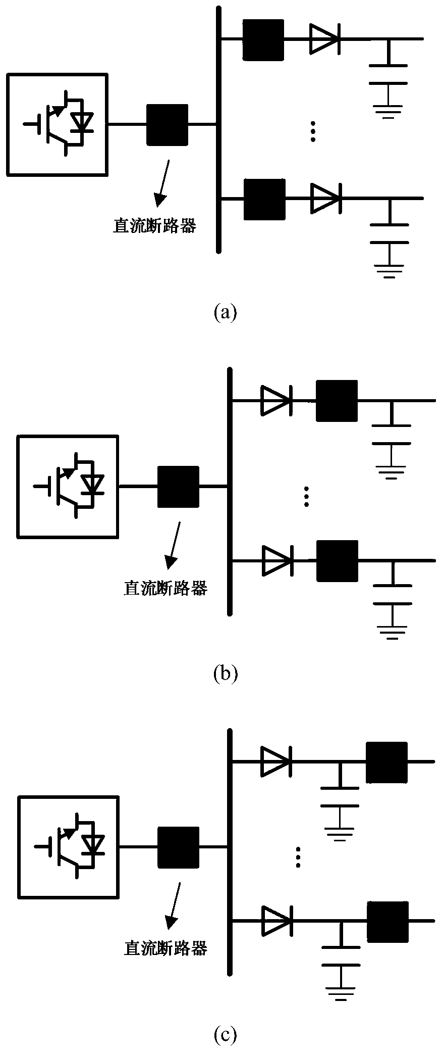
[0015] 1. Cancel the centralized parallel capacitors at the outlet of the DC side of the converter station of the original DC system, distribute and configure line scattered capacitors at the head end of each line connected to the DC bus of the converter station, and increase the capacitance between the DC bus and each distributed capacitor Power diode valve group, the anode of which is connected to the DC bus. The original DC system such as figure 1 As shown in (a), the schematic diagram of the distributed capacitor configuration method in the DC system is as follows: figure 1 (b).

[0016] 2. Define the centralized shunt capacitor C at the outlet of the DC system converter station 0 The design value of is proportional to the maximum power fluctuation of the DC system, and inversely proportional to the allowable limit of the voltage fluctuation of the DC sy...


PUM


Abstract

The invention relates to a fault current limiting method configured by dispersion capacitors of a direct current system. The fault current limiting method comprises the following steps: canceling concentrated parallel capacitors which are arranged at the position of a side outlet on the direct current side of the converter station of an original direct current system, and distributing and configuring circuit dispersion capacitors at the head end of each circuit, connected with the direct current bus of the converter station, of the direct current system, and adding an electric power diode valve group between the direct current bus and each dispersion capacitor, wherein an anode of the electric power diode valve group is connected to the direct current bus; setting a short-circuit fault atf point on a k-th circuit, before the converter station is locked, performing a corresponding protection action on the fault circuit k, and performing actions on direct current circuit breakers of thecircuit k so that the fault circuit is isolated; when the short-circuit fault occurs on the direct current bus at the outlet of the converter station, enabling the bus to perform a protection actionand the direct current breakers connected to all buses to act so that a direct current fault is isolated.

Description

technical field [0001] The invention relates to the field of DC system control and protection. Different from the traditional current limiting measures, this method achieves the purpose of limiting the DC fault current through the DC system capacitor configuration scheme. Background technique [0002] DC fault current limiting and fault isolation are key technologies in the development of DC systems. Due to the small fault damping of the DC system, the rapid development of the fault, and the large fault peak current, strict requirements are placed on the performance of the DC system relay protection and DC circuit breaker. Therefore, it is of great significance to take appropriate measures to delay the fault development speed and limit the fault current level for DC system fault ride-through, safe and stable operation and power supply reliability. At present, the relevant research on fault current limiting of DC systems mostly stays on the innovation and optimization of fa...

Claims


Application Information

Patent Timeline
Patent Type & Authority Patents(China)
IPC IPC(8): H02H7/26H02H7/22
CPCH02H7/22H02H7/268
Inventor 李斌叶仕磊李博通温伟杰
Owner TIANJIN UNIV
Why Eureka
Try Eureka