
IGBT isolation driving circuit with switch control unit and control method thereof

A switch control unit, isolation drive circuit technology, applied in electronic switches, electrical components, pulse technology and other directions, can solve the problem of saturation risk of drive transformer, unipolar operation of carrier pulse, incompatibility with low frequency conditions, etc., to achieve strong practical sexual effect

Pending Publication Date: 2019-03-08
CHENGDU F&M TECH
View PDF1 Cites 5 Cited by
  • Summary
  • Abstract
  • Description
  • Claims
  • Application Information

AI Technical Summary

Problems solved by technology

However, when it is necessary to provide low-frequency turn-on, the half-period carrier pulse is in unipolar operation for a long time, and the driving transformer still faces the risk of saturation
[0008] However, the isolated oscillation demodulation IGBT drive circuit has technical problems such as poor inductance buffering effect, incompatibility with low-frequency working conditions, and narrow application range.

Method used


Image

  • IGBT isolation driving circuit with switch control unit and control method thereof
  • IGBT isolation driving circuit with switch control unit and control method thereof
  • IGBT isolation driving circuit with switch control unit and control method thereof

Examples


Embodiment Construction

[0041] In the following, the present invention will be further described in detail in conjunction with the accompanying drawings and embodiments, so as to make the purpose, technical solutions and advantages of the present invention more clear. It should be understood that the specific embodiments described here are only used to explain the present invention, not to limit the present invention.

[0042] Figure 4It shows an IGBT isolated drive circuit with a switch control unit according to an exemplary embodiment of the present invention, the isolated drive circuit includes: a pulse drive unit that generates a phase-complementary waveform signal, a drive resistor R1, and a turn-off resistor R2 , an insulated gate bipolar transistor (IGBT) Q3, a diode rectifier unit, and a switch control unit. Both the output ends of the drive resistor and the turn-off resistor are connected to the gate of the IGBT (Q3), and the emitter of the IGBT is grounded. The output ends of the drive r...


PUM


Abstract

The invention discloses an IGBT isolation driving circuit with a switch control unit and a control method thereof. The circuit comprises a pulse driving unit for generating waveform signals with complementary phases, a diode rectification unit, the switch control unit, a driving resistor, a switch-off resistor and an insulated gate bipolar transistor (IGBT), output terminals of the driving resistor and the switch-off resistor are both connected with a grid electrode of the IGBT, an emitter electrode of the IGBT is connected to the ground, an input terminal of the switch control unit is connected with the diode rectification unit, and an output terminal of the switch control unit is connected with an input terminal of the switch-off resistor to control cut-off of the IGBT when the pulse driving unit stops signal output. According to the circuit, the driving energy can be transmitted, the transmission of switch signals is completed, cut-off and switch-on of the IGBT can be well controlled through the switch control unit, the circuit can be applicable to a low-frequency condition, and the practicality is high.

Description

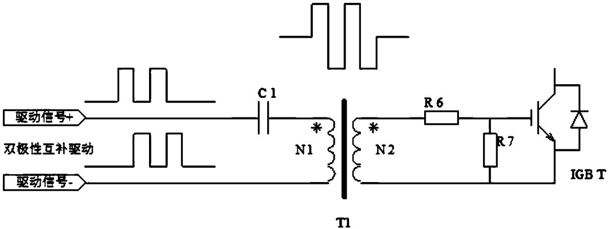
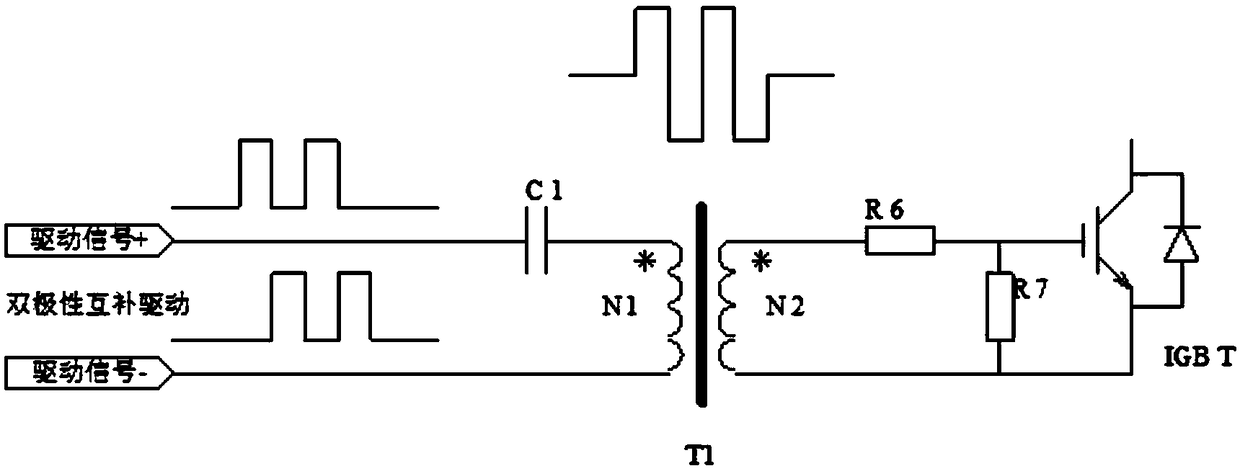
technical field [0001] The invention relates to the technical field of drive circuits, in particular to an IGBT isolation drive circuit with a switch control unit and a control method thereof. Background technique [0002] Current main power devices include MOSFET (Insulated Gate Field Effect Transistor) and IGBT (Insulated Gate Bipolar Transistor), both of which are capacitive gate power devices. Its driving condition is specifically expressed as, when it is turned on, its gate capacitance is charged; when it is turned off, its gate capacitance is discharged. [0003] The basic elements of isolation drive include: drive energy and switching signal. The basic circuit forms of isolation drive include: optocoupler isolation drive and transformer isolation drive. Such as figure 1 As shown, when using the optocoupler isolation driving mode, an independent set of isolated power supply is required to provide energy. The power supply generally needs a power frequency isolation t...

Claims


Application Information

Patent Timeline
Patent Type & Authority Applications(China)
IPC IPC(8): H03K17/567
CPCH03K17/567H03K2217/0081
Inventor 陈果田
Owner CHENGDU F&M TECH
Learn More