A camera module batch focusing test method and system
A technology of camera module and testing method, which is applied in the direction of image communication, television, electrical components, etc., can solve the problems of low production test efficiency, achieve the effects of improving production test efficiency, reducing sampling test points, and reducing test workload
- Summary
- Abstract
- Description
- Claims
- Application Information
AI Technical Summary
Problems solved by technology
Method used
Image
Examples
Embodiment 1
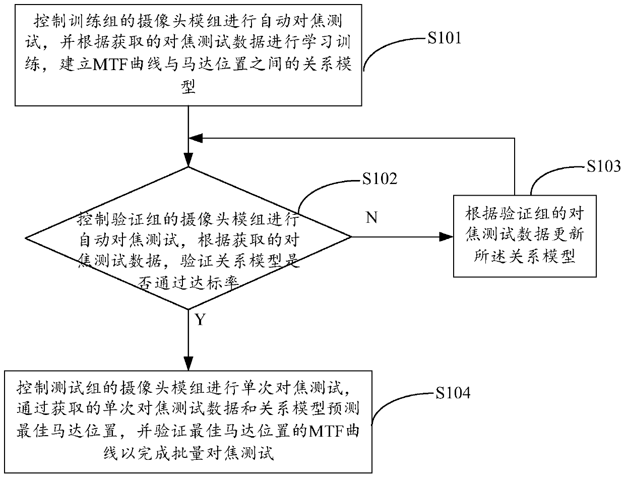
[0035] figure 1 A flow chart showing the implementation of the camera module batch focus testing method provided by Embodiment 1 of the present invention is shown.
[0036] The camera module batch focusing test method provided by the present invention mainly includes the following steps:
[0037] Step S101, controlling the camera module of the training group to perform an autofocus test, and performing learning and training according to the obtained focus test data, and establishing a relationship model between the MTF curve and the motor position;
[0038] In the embodiment of the present invention, the same batch of camera modules to be tested can be divided into: a training group, a verification group and a test group, wherein the number of camera modules in the training group and the verification group is much smaller than that of the test group, and the number of training groups It can be set according to the fineness of the selected neural network, and the number of ver...
Embodiment 2
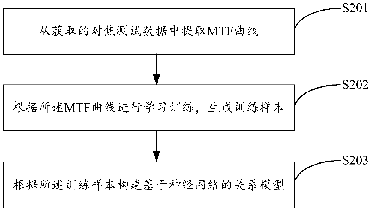
[0058] figure 2 A flow chart showing the implementation of the camera module batch focus testing method provided by Embodiment 2 of the present invention is shown. For ease of description, only parts related to the embodiments of the present invention are shown.
[0059] As a preferred embodiment of the present invention, step S101 in Embodiment 1 can be realized through the following steps:
[0060] Step S201, extracting an MTF curve from the acquired focus test data;
[0061] Step S202, performing learning and training according to the MTF curve to generate training samples;
[0062] Step S203, constructing a neural network-based relational model according to the training samples.
[0063] In the embodiment of the present invention, after learning and training by acquiring the focus test data of the training group, the relationship model between different MTF curves and motor positions can be constructed in the camera module batch focus test system, and the sensitivity o...
Embodiment 3
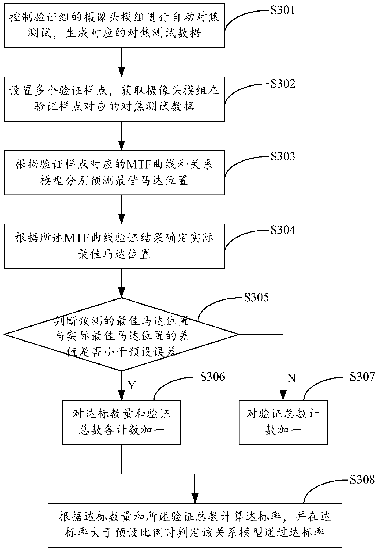
[0065] image 3 A flow chart showing the implementation of the camera module batch focus testing method provided by Embodiment 3 of the present invention is shown. For ease of description, only parts related to the embodiments of the present invention are shown.
[0066] As a preferred embodiment of the present invention, step S102 in Embodiment 1 can be realized through the following steps:
[0067] Step S301, controlling the camera module of the verification group to perform an auto-focus test, and generating corresponding focus test data;
[0068] Step S302, setting a plurality of verification sample points, and obtaining focus test data corresponding to the camera module at the verification sample points, the focus test data including MTF curve, motor position and MTF curve verification results;
[0069] Step S303, respectively predicting the optimal motor position according to the MTF curve corresponding to the verification sample point and the relationship model;
[0...
PUM
 Abstract
Description
Claims
Application Information
 - R&D
- Intellectual Property
- Life Sciences
- Materials
- Tech Scout
- Unparalleled Data Quality
- Higher Quality Content
- 60% Fewer Hallucinations
Browse by: Latest US Patents, China's latest patents, Technical Efficacy Thesaurus, Application Domain, Technology Topic, Popular Technical Reports.
© 2025 PatSnap. All rights reserved.Legal|Privacy policy|Modern Slavery Act Transparency Statement|Sitemap|About US| Contact US: help@patsnap.com


