A fixture for processing the steel back of a brake pad

A technology for brake pads and steel backs, which is applied in the field of fixtures for processing brake pad steel backs, can solve problems such as vibration, reduced efficiency of grinding devices, and inability to fix the steel back of brake pads, etc., to reduce vibration, facilitate grinding production, and improve production efficiency Effect

Active Publication Date: 2020-09-08
温州市钢泰冲压件有限公司
View PDF5 Cites 0 Cited by
  • Summary
  • Abstract
  • Description
  • Claims
  • Application Information

AI Technical Summary

Problems solved by technology

[0004] During the production process of automobiles, multiple parts are required to complete the assembly, especially the steel back parts of the brake pads are more important. During the production process of the steel backs of the brake pads, the front and back of the steel backs of the brake pads need to be polished, but the existing brake pads The grinding device for the steel back of the brake pad cannot effectively fix the steel back of the brake pad during the grinding process, and the steel back of the brake pad will vibrate with the grinding equipment during grinding, resulting in a decrease in the efficiency of the grinding device, and the steel back of the brake pad In the grinding process, the steel back of the brake pad needs to be turned over at any time, and the existing technology needs to fix the steel back of the brake pad after turning over the steel back, so that the overall production efficiency is low. fixture

Method used


Image

  • A fixture for processing the steel back of a brake pad
  • A fixture for processing the steel back of a brake pad
  • A fixture for processing the steel back of a brake pad

Examples


Embodiment Construction

[0021] The technical solutions in the embodiments of the present invention will be clearly and completely described below in conjunction with the accompanying drawings in the embodiments of the present invention. Obviously, the described embodiments are only part of the embodiments of the present invention, not all of them.

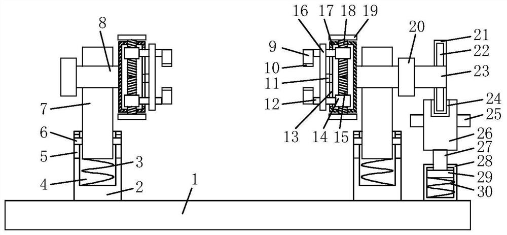
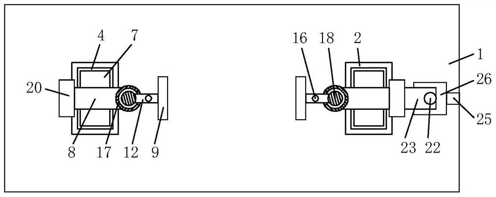
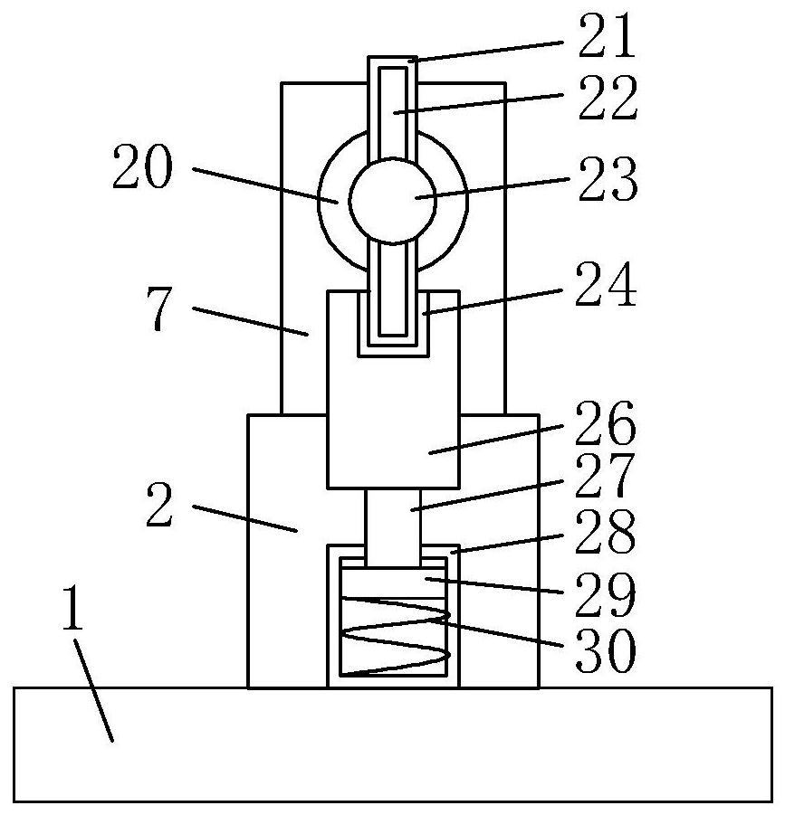
[0022] refer to Figure 1-3 , a fixture for processing the steel back of a brake pad, comprising a support platform 1, two support plates 2 are fixedly arranged on the upper side of the support platform 1, and the two support plates 2 are arranged at intervals from each other, and the upper sides of the two support plates 2 are all passed through reducing The shock mechanism is connected with a supporting plate 2, and the shock absorbing mechanism includes a plate groove 4 provided on the upper side of the supporting plate 2, and an inserting plate 7 is inserted in the plate groove 4, and the inserting plate 7 is matched with the plate groove 4, and the in...


PUM


Abstract

The invention relates to the technical field of automobiles, in particular to a clamp for machining a brake pad steel backing. Two supporting plates are fixedly arranged on the upper side of a supporting table and spaced, the upper sides of the two supporting plates are connected with supporting plates through damping mechanisms, rotary shafts penetrate through the upper ends of the two supportingplates, limiting plates are fixed to the sides, away from each other, of the two rotary shafts, fixing mechanisms are arranged on the corresponding sides of the two rotary shafts, a connecting rod isconnected to the outer side of one limiting plate, turnover rods are arranged at the upper end and the lower end of the connecting rod, and the turnover rods are limited through clamping mechanisms.The brake pad steel backing can be rapidly fixed and clamped, the fixing efficiency is good, and by means of the buffer capacity brought by the arranged damping mechanisms, vibration generated duringgrinding production of the brake pad steel backing can be effectively relieved; and by means of the arranged turnover rods, the fixed brake pad steel backing can be rapidly rotated, thus, grinding production can be conveniently carried out on the front face and the rear face of the brake pad steel backing, and the production efficiency of the brake pad steel backing is improved.

Description

technical field [0001] The invention relates to the technical field of automobiles, in particular to a clamp for processing the steel back of a brake pad. Background technique [0002] Automobile has the following definition in the latest national standard "Terms and Definitions of Automobile and Trailer Types": a non-rail-mounted vehicle driven by power with 4 or more wheels, mainly used for: carrying people and (or) Goods; vehicles towing people and / or goods; special purpose. [0003] In my country, a car refers to a vehicle that is driven by a power unit with its own equipment, generally has four or more wheels, and does not rely on rails or wires to drive on land. Automobiles are usually used to carry passengers, goods, and tow passengers and goods trailers. They are also converted into special vehicles or equipped with special equipment to complete specific transportation tasks or work tasks, but they do not include machinery specially used for agriculture. [0004] D...

Claims


Application Information

Patent Timeline
Patent Type & Authority Patents(China)
IPC IPC(8): B24B41/06
CPCB24B41/06
Inventor 董海卓
Owner 温州市钢泰冲压件有限公司
Why Eureka
Try Eureka