Carbon-heat co-production boiler of straw particle fuel

A granular fuel and carbon heat technology, applied in the boiler field, can solve the problems of inconvenient adjustment of feed speed and feed volume, and achieve the effect of easy adjustment, convenient use, and adjustment of combustion intensity

Pending Publication Date: 2019-03-12
JIANGSU YUANHE AUTOMATION TECH
View PDF0 Cites 0 Cited by
  • Summary
  • Abstract
  • Description
  • Claims
  • Application Information

AI Technical Summary

Problems solved by technology

[0004] The purpose of the present invention is to provide a carbon-heat cogeneration boiler with straw pellet fuel. By opening multiple rows of insertion holes on the arc-shaped plate, and adjusting the blocking material through the cooperation of the horizontal plate, the arc-shaped plate, the rotating shaft and the through hole The angle of the plate can fix the position of the arc-shaped plate and the blocking plate by installing a fixing device. The discharge channel is formed through the cooperation of the blocking plate, the first material guide plate and the second material guide plate. By turning over the blocking plate The size of the discharge channel can be adjusted, which solves the problem that the existing boiler feed rate and feed volume are not easy to adjust

Method used


Image

  • Carbon-heat co-production boiler of straw particle fuel
  • Carbon-heat co-production boiler of straw particle fuel
  • Carbon-heat co-production boiler of straw particle fuel

Examples


Embodiment Construction

[0031] The following will clearly and completely describe the technical solutions in the embodiments of the present invention with reference to the accompanying drawings in the embodiments of the present invention. Obviously, the described embodiments are only some, not all, embodiments of the present invention. Based on the embodiments of the present invention, all other embodiments obtained by persons of ordinary skill in the art without creative efforts fall within the protection scope of the present invention.

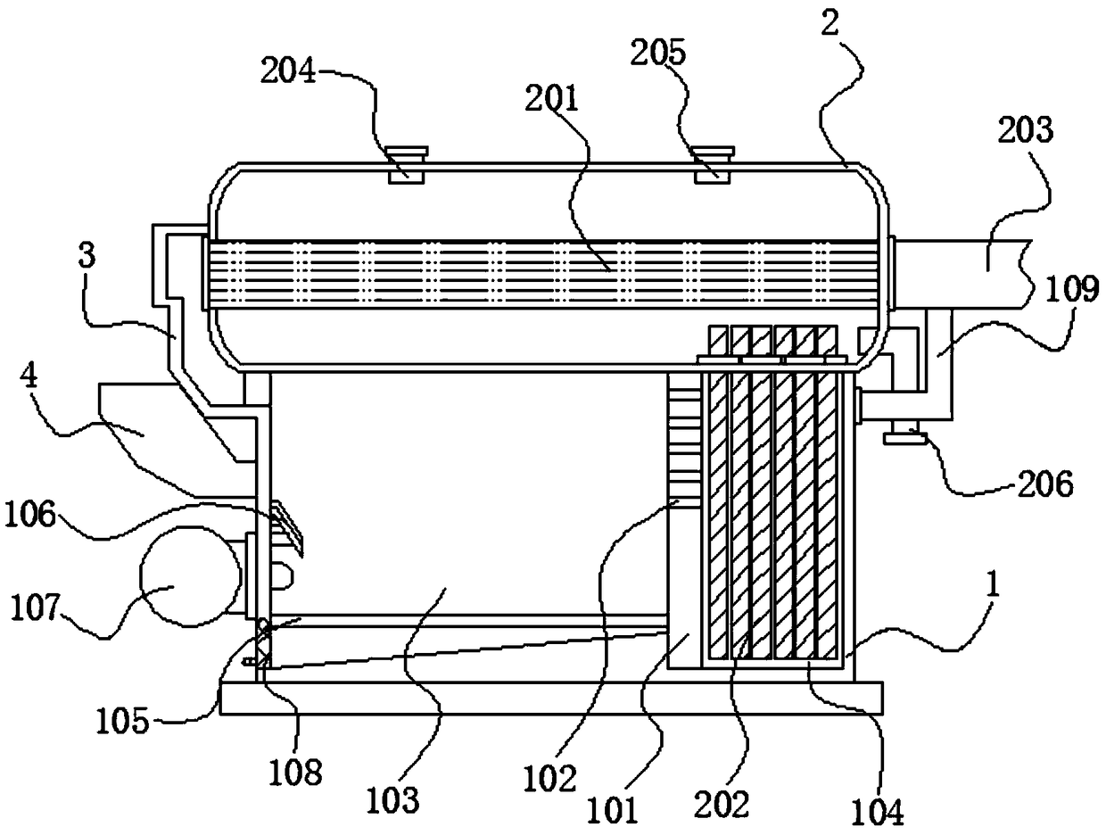
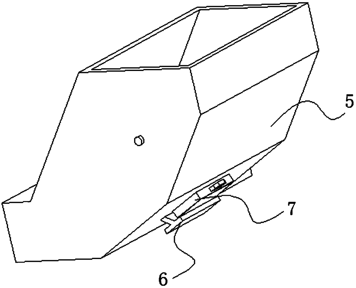
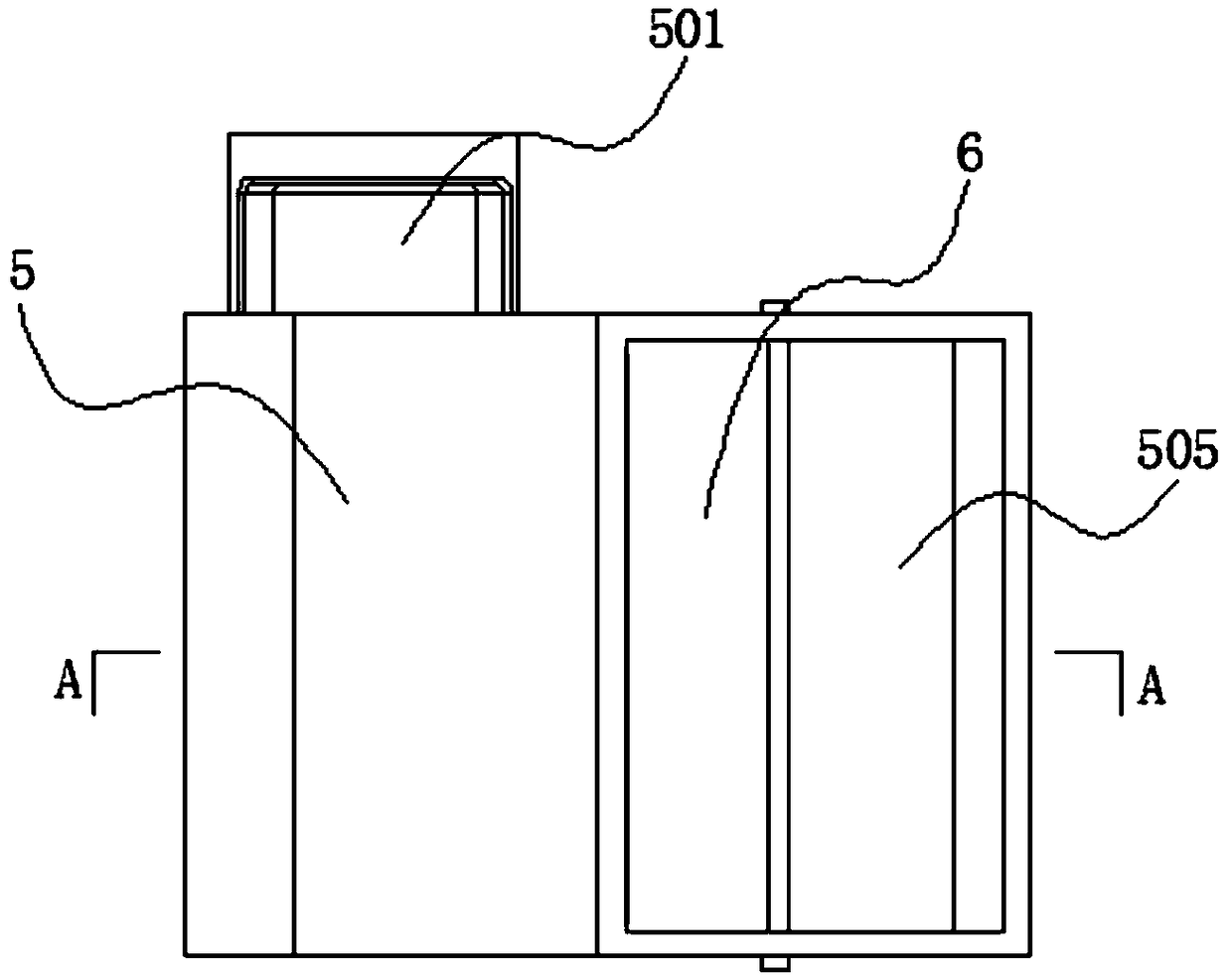
[0032] see Figure 1-6 As shown, the present invention is a carbon-heat cogeneration boiler of straw pellet fuel, comprising a furnace body 1, a water tank 2 is fixed on the top of the furnace body 1, a partition 101 is fixed inside the furnace body 1, and twenty A through hole 102, the body of heater 1 is divided into a combustion chamber 103 and a heat conduction chamber 104 by a dividing plate 101;

[0033] One side of the water tank 2 and one side of the furna...


PUM


Abstract

The invention discloses a carbon-heat co-production boiler of straw particle fuel, and relates to the technical field of boilers. The device comprises a furnace body, a water tank is fixed at the topof the furnace body, a partition plate is fixed in the furnace body, and twenty through holes are formed in the partition plate. The furnace body is divided into a combustion chamber and a heat conduction chamber through the partition plate, a gas guide shell is fixed to one side of the water tank and one side of the furnace body, a gas inlet of the gas guide shell communicates with one side of the combustion chamber, and a tubular heat exchanger is fixedly arranged on the water tank in a penetrating mode. A plurality of rows of inserting holes are formed in an arc-shaped plate, and a transverse plate, the arc-shaped plate, a rotating shaft and the through holes are cooperatively used so as to adjust the angle of a material blocking plate. The positions of the arc-shaped plate and the material blocking plate can be fixed through a fixing device. Through cooperation of the material blocking plate, a first material guide plate and a second material guide plate, a discharging channel is formed. The size of the discharging channel can be adjusted by turning the material blocking plate, and the problem that the feeding speed and feeding amount of an existing boiler are inconvenient to adjust is solved.

Description

technical field [0001] The invention belongs to the technical field of boilers, in particular to a boiler for cogeneration of carbon and heat with straw particle fuel. Background technique [0002] A boiler is an energy conversion device. The energy input to the boiler includes chemical energy and electric energy in the fuel. The boiler outputs steam, high-temperature water or organic heat carrier with a certain amount of heat energy. The original meaning of the pot refers to a water container heated on fire. Furnace refers to the place where fuel is burned. The boiler includes two parts: the boiler and the furnace. The hot water or steam generated in the boiler can directly provide the required heat energy for industrial production and people's life, and can also be converted into mechanical energy through a steam power device, or regenerated. The mechanical energy is converted into electrical energy by a generator. [0003] The traditional straw pellet fuel boiler adopts ...

Claims


Application Information

Patent Timeline
Patent Type & Authority Applications(China)
IPC IPC(8): F22B31/00F24H1/36F23K3/00F23N1/00
CPCF22B31/00F23K3/00F23N1/007F24H1/36
Inventor 孙芹珍殷硕周鑫
Owner JIANGSU YUANHE AUTOMATION TECH
Why Eureka
Try Eureka