Power transmission tower defect identification method based on high-accuracy positioning multi-rotor unmanned aerial vehicle

A technology of multi-rotor UAV and power transmission tower, which is applied in the direction of optical test defect/defect, vehicle position/route/height control, non-electric variable control, etc., which can solve the problem of automatic image processing and image The shooting angle and quality cannot be guaranteed, and the hovering accuracy is restricted, so as to achieve the effect of realizing high-precision control, reducing the amount of calculation, and eliminating interference

Inactive Publication Date: 2019-03-12
TIANJIN RICHSOFT ELECTRIC POWER INFORMATION TECH +1
View PDF7 Cites 8 Cited by
  • Summary
  • Abstract
  • Description
  • Claims
  • Application Information

AI Technical Summary

Problems solved by technology

However, at present, it is still mainly relying on personnel to manually operate drones to carry out inspections, which are greatly affected by factors such as personnel operating experience, skill level, and environmental mutations. There are problems such as low inspection efficiency and poor stability. and other differences, resulting in large differences in the images captured by inspections
Although there are currently unmanned aerial vehicle devices capable of fixed-point flight and shooting, due to the hovering accuracy, the shooting angle and quality of the image cannot be guaranteed, and it is impossible to obtain images with a consistent phase height for automatic processing

Method used


Image

  • Power transmission tower defect identification method based on high-accuracy positioning multi-rotor unmanned aerial vehicle

Examples


Embodiment Construction

[0028] The technical solutions of the present invention will be further described in detail below with reference to the drawings and embodiments. However, it should be understood that these drawings are only designed for explanatory purposes, and therefore are not intended to limit the scope of the present invention. In addition, unless otherwise noted, these drawings are only intended to conceptually illustrate the structure described herein, and are not necessarily drawn to scale.

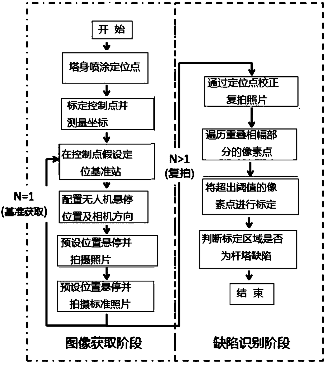
[0029] Combine below figure 1 The present invention will be explained in detail.

[0030] A method for identifying defects in a transmission tower of a multi-rotor UAV based on high-precision positioning includes the following steps:

[0031] 1. Spray three positioning points around the base of the transmission tower, the nameplate, and the tower body at the tower head.

[0032] Spray three white positioning points on the tower body. The shape of the map frame determined by the three positioning points ...


PUM


Abstract

The invention discloses a power transmission tower defect identification method based on a high-accuracy positioning multi-rotor unmanned aerial vehicle. The power transmission tower defect identification method comprises the following steps: (1) spraying a positioning point to a tower body in a power transmission tower patrolling region; (2) calibrating a control point in a surface stabilizationregion and measuring the coordinates of the control point; (3) erecting a ground reinforcement positioning reference station at the control point; (4) setting three-dimensional coordinates and a lensdirection for hovering the multi-rotor unmanned aerial vehicle, and starting the multi-rotor unmanned aerial vehicle; (5) hovering the unmanned aerial vehicle at a fixed position, calibrating a shooting direction through the positioning point, and shooting and numbering N pictures; (6) when the patrolling work is carried out, repeating the operations in the steps (3) to (5) to acquire reshot images; (7) respectively correcting the N reshot pictures according to a standard picture through the positioning point; (8) traversing pixel points of overlapped phase-and-amplitude parts of the corresponding pictures by using an image identification program; (9) calibrating areas having a pixel difference exceeding a threshold value; and (10) judging whether the calibrated part is a tower defect or adefect prewarning. By the power transmission tower defect identification method, equipment defects can be found early, so as to improve the refining and standardizing degree of the patrol work.

Description

Technical field [0001] The invention belongs to the technical field of power equipment detection, and particularly relates to the field of patrol inspection of power transmission towers based on drones and image recognition. Background technique [0002] The inspection of transmission towers is an important part of the daily operation and maintenance of transmission lines. In recent years, multi-rotor UAVs have become an important means of fine inspections of transmission lines due to their high precision inspections. However, at present, personnel still mainly rely on manual operation of drones to conduct inspections, which are greatly affected by factors such as personnel operating experience, skill level, and sudden changes in the environment. There are problems such as low inspection efficiency and poor stability. At the same time, due to inspection paths and shooting locations And other differences, resulting in larger differences in the images taken during inspections. Alt...

Claims


Application Information

Patent Timeline
Patent Type & Authority Applications(China)
IPC IPC(8): G01N21/88G05D1/10
CPCG01N21/88G05D1/101
Inventor 陈文康周航帆赵光俊王汝英潘飚熊道洋李君海刘畅于婷
Owner TIANJIN RICHSOFT ELECTRIC POWER INFORMATION TECH
Why Eureka
Try Eureka