Automatic freezing point tester and testing method

A test method and measuring instrument technology, applied in the investigation stage/state change, etc., can solve the problems of different thermal conductivity between the outer wall and the center of the container, the temperature deviation between the center of the oil and the outside, and the limitation of the detection structure, so as to prevent oil Stratified, increased contact area, the same effect of purity

Active Publication Date: 2019-03-12
QUANZHOU QUANTONG PHOTOELECTRIC TECH
View PDF32 Cites 2 Cited by
  • Summary
  • Abstract
  • Description
  • Claims
  • Application Information

AI Technical Summary

Problems solved by technology

[0002] The freezing point is one of the important parameters of petroleum products. It is mainly used in the analysis of aviation fuel oil products. The testing of the freezing point parameters of petroleum products can be tested by manual or automatic instruments. Now the commercially available automatic freezing point testers are generally divided into two types. Different test methods refer to different technical standards. Regardless of the method, the oil to be tested in the container is continuously cooled through the coolant until it reaches the freezing point of the oil; this type of method has great disadvantages, that is, the container The temperature transfer between the outer wall and the center will be due to the different thermal conductivity of the oil to be tested, resulting in a large deviation in the temperature between the center and the outside of the oil, and reducing the detection amount of the oil to be tested will limit the detection structure

Method used


Image

  • Automatic freezing point tester and testing method
  • Automatic freezing point tester and testing method
  • Automatic freezing point tester and testing method

Examples


Embodiment Construction

[0035] In order to further understand the structure, features and other purposes of the present invention, the attached preferred embodiments are now described in detail with accompanying drawings as follows. The embodiments described in the accompanying drawings are only used to illustrate the technical solutions of the present invention and are not limiting this invention.

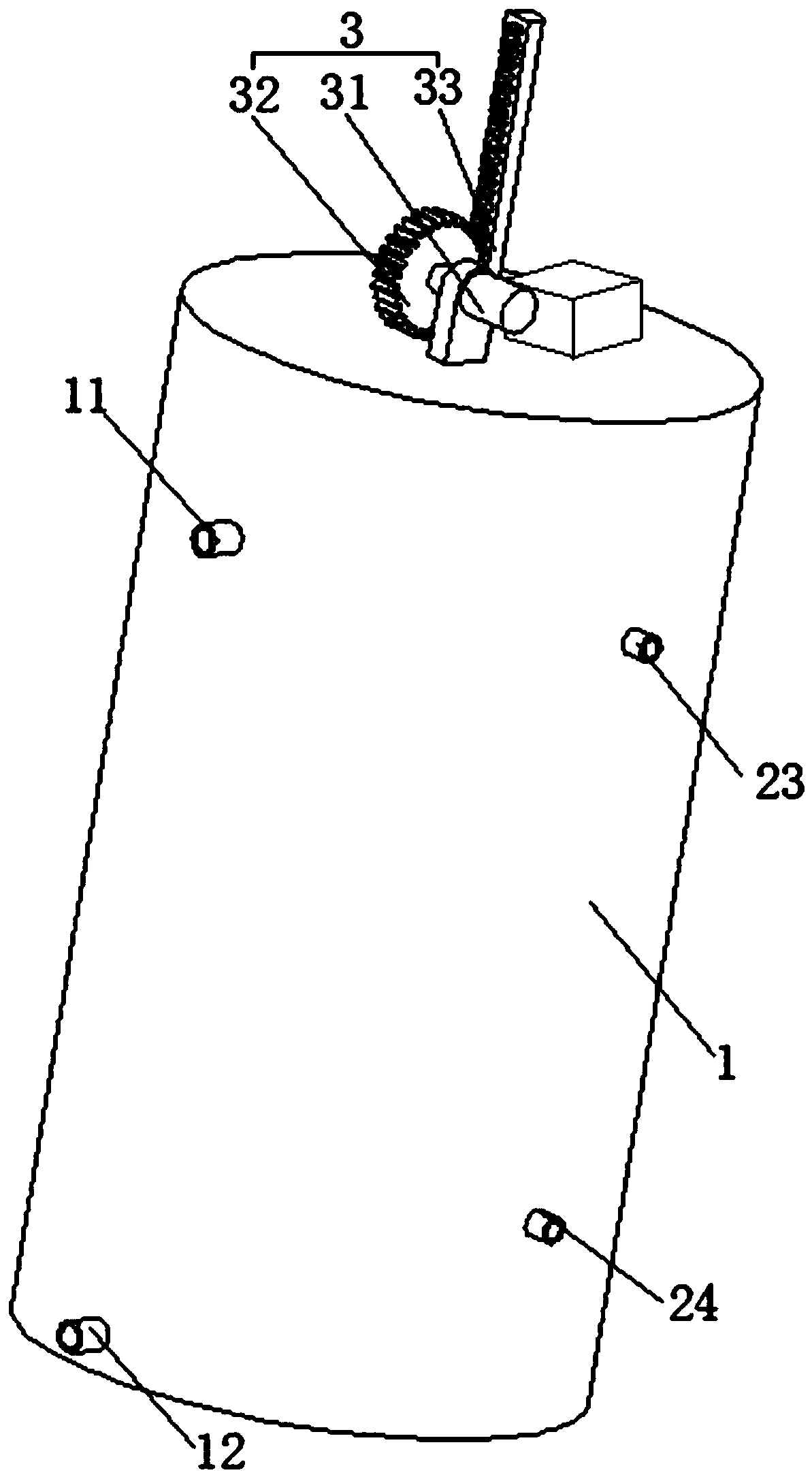
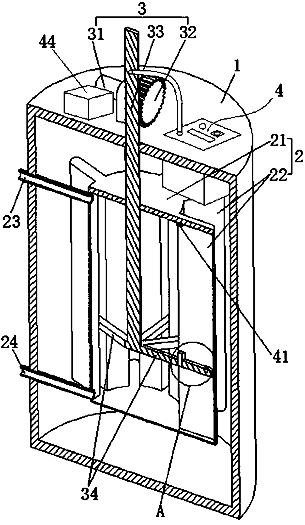
[0036] An automatic freezing point measuring instrument, combined with figure 1 , figure 2, including an outer cylinder 1, an inner cylinder 2, and a stirring member 3, the outer cylinder 1 is cylindrical, the inner cylinder 2 is fixedly connected in the outer cylinder 1, the outer diameter of the inner cylinder 2 is smaller than the inner diameter of the outer cylinder 1, and the upper end of the outer cylinder 1 is fixed A liquid inlet pipe 11 is connected, and a liquid outlet pipe 12 is fixedly connected to the lower end of the same side of the outer cylinder 1. A coolant flows inside the liquid inl...


PUM


Abstract

The invention provides an automatic freezing point tester and a testing method. The automatic freezing point tester comprises an outer barrel, an inner barrel and a stirring part. The inner barrel comprises a cylinder and a plurality of swing barrels, the swing barrels are fixedly connected at annular intervals to the outer periphery of the cylinder, the length of each swing barrel is two thirds of the diameter of the cylinder, an angle between every two adjacent swing barrels is 40 degrees, and the swing barrels are communicated with the cylinder. The stirring part comprises a motor, a gear and a stirring rod, the motor is fixedly connected to the top of the outer barrel, the gear is in rotational connection with an output end of the motor, the stirring rod penetrates the outer barrel toextend into the inner barrel, radial stirring blades are fixedly connected to the bottom of the stirring rod and extend into the swing barrels, and the width of each stirring blade is three fourths ofthat of the inner side of each swing barrel. One side of the stirring rod is provided with a plane which is fixedly connected with a rack, and the rack is meshed with the gear to enable the stirringrod to move up and down. By total refrigeration of to-be-tested oil, high cooling efficiency is realized, identical internal and external temperatures of the to-be-tested oil are guaranteed, detectionaccuracy is improved, and accuracy of a primary measurement result reaches 0.1 DEG C.

Description

technical field [0001] The invention relates to the field of detection equipment, in particular to an automatic freezing point measuring instrument and a testing method thereof. Background technique [0002] The freezing point is one of the important parameters of petroleum products. It is mainly used in the analysis of aviation fuel oil products. The testing of the freezing point parameters of petroleum products can be tested by manual or automatic instruments. Now the commercially available automatic freezing point testers are generally divided into two types. Different test methods refer to different technical standards. Regardless of the method, the oil to be tested in the container is continuously cooled through the coolant until it reaches the freezing point of the oil; this type of method has great disadvantages, that is, the container The temperature transfer between the outer wall and the center will be due to the different thermal conductivity of the oil to be test...

Claims


Application Information

Patent Timeline
Patent Type & Authority Applications(China)
IPC IPC(8): G01N25/04
CPCG01N25/04
Inventor 蔡丽娜黄金兴洪杰辉
Owner QUANZHOU QUANTONG PHOTOELECTRIC TECH
Why Eureka
Try Eureka