Clean type waste cable stripping machine

A waste cable, clean technology, applied in the field of electric power, can solve the problem of inconvenient separation of the copper core and protective layer of the cable

Active Publication Date: 2019-03-12
浙江恩威电气有限公司
View PDF6 Cites 7 Cited by
  • Summary
  • Abstract
  • Description
  • Claims
  • Application Information

AI Technical Summary

Problems solved by technology

[0004] In order to overcome the shortcomings that the cleaning of the cable surface requires a lot of manpower and material resources, and the copper core and the protective layer of the cable are not easy to separate, the technical problem to be solved by ...

Method used


Image

  • Clean type waste cable stripping machine
  • Clean type waste cable stripping machine
  • Clean type waste cable stripping machine

Examples


Embodiment

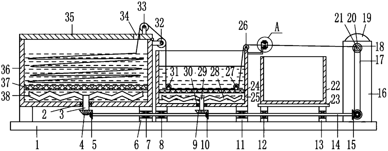
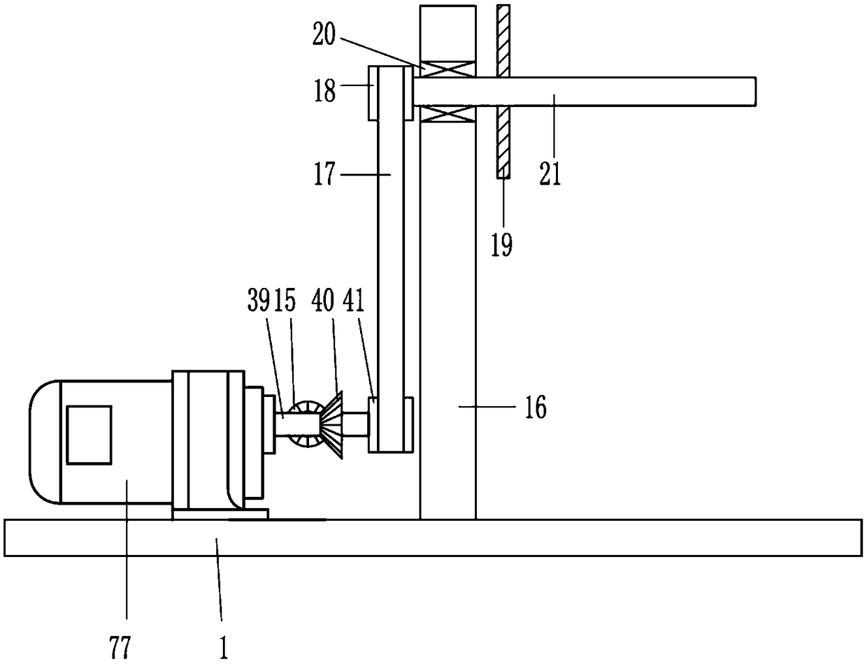
[0032] A clean type waste cable stripping machine, such as Figure 1-11As shown, it includes a bottom plate 1, a first bearing seat 2, a first rotating shaft 3, a first bevel gear 4, a second bevel gear 5, a first support seat 6, a second bearing seat 7, a third bearing seat 8, a first bevel gear Three bevel gears 9, the fourth bevel gear 10, the second support seat 11, the fourth bearing seat 12, the third support seat 13, the second rotating shaft 14, the fifth bevel gear 15, the mounting plate 16, the flat belt 17, the first Pulley 18, first limit disc 19, fifth bearing seat 20, third rotating shaft 21, collection frame 22, placement plate 23, first mesh plate 24, first cleaning frame 25, first guide wheel 26, second guide Wheel 27, first stirring blade 28, fourth rotating shaft 29, sixth bearing seat 30, third guide wheel 31, fourth guide wheel 32, fifth guide wheel 33, cover plate 35, second cleaning frame 36, second Net plate 37, the second stirring blade 38, the fifth ...


PUM


Abstract

The invention belongs to the field of electric power, and particularly relates to a clean type waste cable stripping machine. The technical problem to be solved by the invention is to provide a cleantype waste cable stripping machine which can facilitate the separation of a protective layer and a copper core of a cable, reduce the workload of a worker, and can quickly clean the surface of the cable. The clean type waste cable stripping machine comprises a bottom plate, a first bearing seat, a cutting blade and an L-shaped mounting rod; a second cleaning frame is fixedly connected to the top of the bottom plate through a first supporting seat, a first cleaning frame is fixedly connected to the top of the bottom plate through a second supporting seat, a placement plate is fixedly connectedto the top of the bottom plate through a third supporting seat, a collection frame is placed on the top of the placement plate, and the first cleaning frame is located between the second cleaning frame and the collection frame. The clean type waste cable stripping machine provided by the invention achieves thorough surface cleaning of the waste cable and can conveniently achieve a rapid separationeffect of a cable sheath and the cable copper core.

Description

technical field [0001] The invention belongs to the field of electric power, in particular to a clean type waste cable stripping machine. Background technique [0002] After the cable is used for a long time, the conductivity of the copper core will be reduced, the insulation of the cable sheath will be deteriorated, and a short circuit will occur. At this time, it is necessary to replace the new cable and replace the original old cable. The copper core of the cable can be used again after recycling. For this reason, some manufacturers specialize in the recycling of waste cables to strip the copper core. At present, the recycling of these copper cores is generally done manually by workers or by fire. Slower, and the labor intensity of the workman is bigger, adopts the method for burning to cause the damage of copper core easily, and burning cable sheath produces poisonous gas, causes environmental pollution. [0003] After the cable is recycled, a lot of dirt and stains are...

Claims


Application Information

Patent Timeline
IPC IPC(8): H01B15/00H02G1/12B08B1/02B08B3/04B08B3/10
CPCB08B1/02B08B3/041B08B3/102H01B15/00H01B15/006H02G1/126Y02W30/82
Inventor 不公告发明人
Owner 浙江恩威电气有限公司
Why Eureka
Try Eureka