Oil removing machine for grip of moving spanner of car

A technology of adjustable wrench and handle, applied in cleaning methods and utensils, cleaning methods using tools, chemical instruments and methods, etc., can solve problems such as low work efficiency and cumbersome operation process, and achieve high work efficiency and simple operation Effect

Inactive Publication Date: 2019-03-15
钟超
View PDF5 Cites 6 Cited by
  • Summary
  • Abstract
  • Description
  • Claims
  • Application Information

AI Technical Summary

Problems solved by technology

[0003] In order to overcome the shortcomings of people holding an adjustable wrench in one hand and a brush in the other hand to continuously scrub the handle of the adjustable wrench to remove oil, the operation process is cumbersome and the work efficiency is low. Therefore, the technical problem of the present invention is: to provide an operation Simple, high-efficiency automobile adjustable wrench grip degreaser

Method used


Image

  • Oil removing machine for grip of moving spanner of car
  • Oil removing machine for grip of moving spanner of car
  • Oil removing machine for grip of moving spanner of car

Examples


Embodiment 1

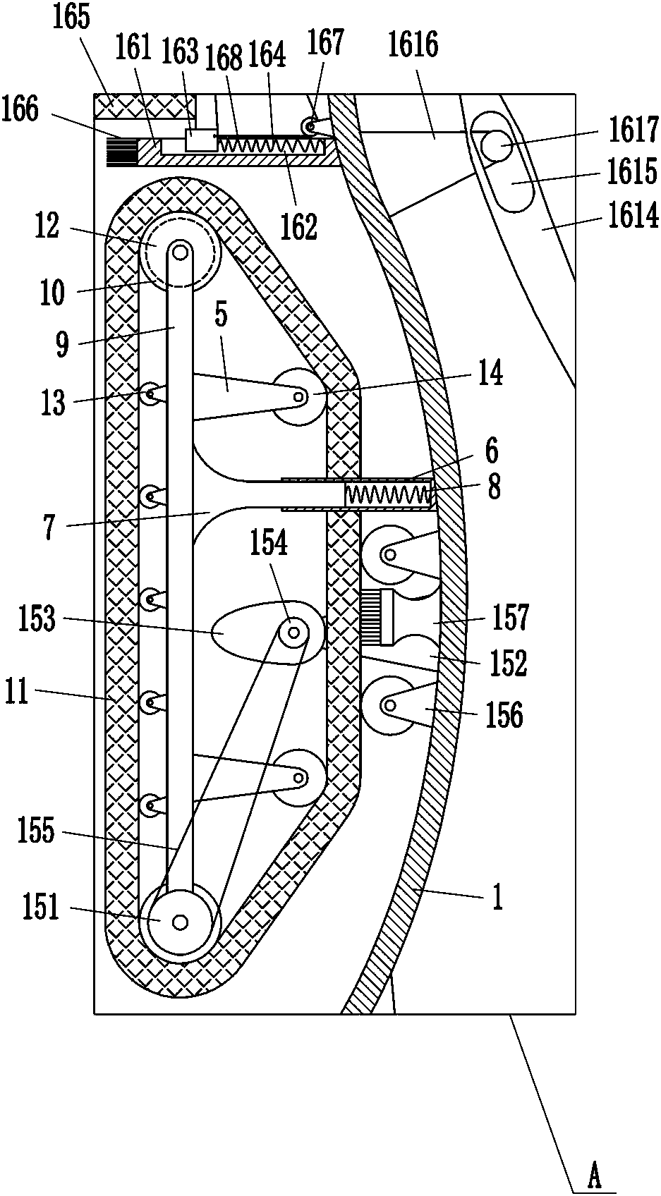
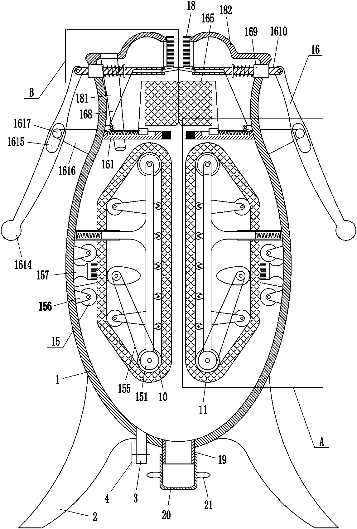
[0021] A kind of automobile adjustable wrench handle degreasing machine, such as Figure 1-3As shown, it includes box body 1, outrigger 2, drain pipe 3, valve 4, installation seat 5, sleeve 6, sleeve rod 7, first spring 8, installation frame 9, roller 10, sponge conveyor belt 11, motor 12. Small support roller 13, large support roller 14 and scrubbing mechanism 15, outriggers 2 are fixedly connected to the left and right sides of the bottom of the box body 1, and the drain pipe 3 is connected to the left side of the bottom of the box body 1, and the drain pipe 3 is located on the left side of the support. On the right side of the leg 2, a valve 4 is installed on the drain pipe 3, and the left and right sides of the middle part of the box body 1 are connected with a square sleeve 6, and the sleeve 6 is provided with a square sleeve rod 7, the sleeve rod 7 and the inner wall of the sleeve 6 are connected with a first spring 8, and the inner ends of the two sleeve rods 7 are conn...

Embodiment 2

[0023] A kind of automobile adjustable wrench handle degreasing machine, such as Figure 1-3 As shown, it includes box body 1, outrigger 2, drain pipe 3, valve 4, installation seat 5, sleeve 6, sleeve rod 7, first spring 8, installation frame 9, roller 10, sponge conveyor belt 11, motor 12. Small support roller 13, large support roller 14 and scrubbing mechanism 15, outriggers 2 are fixedly connected to the left and right sides of the bottom of the box body 1, and the drain pipe 3 is connected to the left side of the bottom of the box body 1, and the drain pipe 3 is located on the left side of the support. On the right side of the leg 2, a valve 4 is installed on the drain pipe 3, and the left and right sides of the middle part of the box body 1 are connected with a square sleeve 6, and the sleeve 6 is provided with a square sleeve rod 7, the sleeve rod 7 and the inner wall of the sleeve 6 are connected with a first spring 8, and the inner ends of the two sleeve rods 7 are con...

Embodiment 3

[0026] A kind of automobile adjustable wrench handle degreasing machine, such as Figure 1-3 As shown, it includes box body 1, outrigger 2, drain pipe 3, valve 4, installation seat 5, sleeve 6, sleeve rod 7, first spring 8, installation frame 9, roller 10, sponge conveyor belt 11, motor 12. Small support roller 13, large support roller 14 and scrubbing mechanism 15, outriggers 2 are fixedly connected to the left and right sides of the bottom of the box body 1, and the drain pipe 3 is connected to the left side of the bottom of the box body 1, and the drain pipe 3 is located on the left side of the support. On the right side of the leg 2, a valve 4 is installed on the drain pipe 3, and the left and right sides of the middle part of the box body 1 are connected with a square sleeve 6, and the sleeve 6 is provided with a square sleeve rod 7, the sleeve rod 7 and the inner wall of the sleeve 6 are connected with a first spring 8, and the inner ends of the two sleeve rods 7 are con...


PUM


Abstract

The invention relates to an oil removing machine, in particular to an oil removing machine for a grip of a moving spanner of a car. Therefore, according to the technical problem, the car moving spanner grip oil removing machine is easy to operate and high in working efficiency. According to the technical implementation scheme, the oil removing machine for the grip of the moving spanner of the carcomprises a box body, supporting legs, a water drainage pipe, a valve, an installing base, a sleeve, a sleeve rod, a first spring, an installing frame, a roller, a sponge conveying belt, a motor, a small supporting roller and the like, the supporting legs are fixedly connected to the left side and the right side of the bottom of the box body correspondingly, the water drainage pipe is connected tothe left side of the bottom of the box body, the water drainage pipe is located on the right side of the supporting leg on the left side, and the valve is installed on the water drainage pipe. According to the oil removing machine, the motor can drive the sponge conveying belt to rotate to remove oil on the grip of the moving spanner, thus, operation is simple, and the working efficiency is high.By means of a scrubbing mechanism, oil stain on the sponge conveying belt can be brushed off, and thus the sponge conveying belt can remove the oil on the grip of the moving spanner more thoroughly.

Description

technical field [0001] The invention relates to an oil removal machine, in particular to an automobile adjustable wrench handle oil removal machine. Background technique [0002] In the process of car maintenance, an adjustable wrench is often used. After the adjustable wrench has been used for a long time, the handle of the adjustable wrench will be stained with more oil. In order not to affect the use, it is necessary to degrease the handle of the adjustable wrench. Nowadays, people generally hold an adjustable wrench in one hand and a brush in the other hand to continuously scrub the handle of the adjustable wrench to remove oil. In the process of scrubbing the adjustable wrench, it is necessary to pour water with detergent on the handle of the adjustable wrench from time to time. In this way, the operation process is cumbersome and the work efficiency is low; in order to improve work efficiency, people will pour water and detergent into the container according to the app...

Claims


Application Information

Patent Timeline
Patent Type & Authority Applications(China)
IPC IPC(8): B08B1/00B08B13/00B08B1/02
CPCB08B1/002B08B1/006B08B1/007B08B1/02B08B13/00
Inventor 钟超
Owner 钟超
Why Eureka
Try Eureka