Clamp tool for scroll plate milling and using method thereof

A scroll and milling technology, applied in the direction of clamping devices, clamping, positioning devices, etc., can solve the problems of large machining errors, low production efficiency, inconvenient operation, etc., to eliminate the impact, prevent excessive extension, Guarantee the effect of clamping effect

Active Publication Date: 2019-03-15
MAANSHAN AOTEJIA MECHANICAL & ELECTRICAL CO LTD +2
View PDF12 Cites 0 Cited by
  • Summary
  • Abstract
  • Description
  • Claims
  • Application Information

AI Technical Summary

Problems solved by technology

[0003] Most of the existing scroll milling fixtures use hydraulic, pneumatic or electric chucks, all of which only clamp the bottom of the scroll. This clamping method has disadvantages: when the tool is milling the scroll When the blank is turned, the tool will apply a large cutting force to the inner or outer wall of the scroll to cut the margin, and the blank will tend to move with the tool, and the chuck will exert force on the bottom of the scroll, resulting in vortex There is a large machining error in the machining surface of the disc blank
Moreover, most of the existing fixtures cannot realize the rapid transformation of the fixture tooling between the shapes of different scroll bottoms, and need to replace the fixtures for processing, which is inconvenient to operate and low in production efficiency
It cannot meet the needs of the factory to produce a variety of scroll bottom structures

Method used


Image

  • Clamp tool for scroll plate milling and using method thereof
  • Clamp tool for scroll plate milling and using method thereof
  • Clamp tool for scroll plate milling and using method thereof

Examples


Embodiment 1

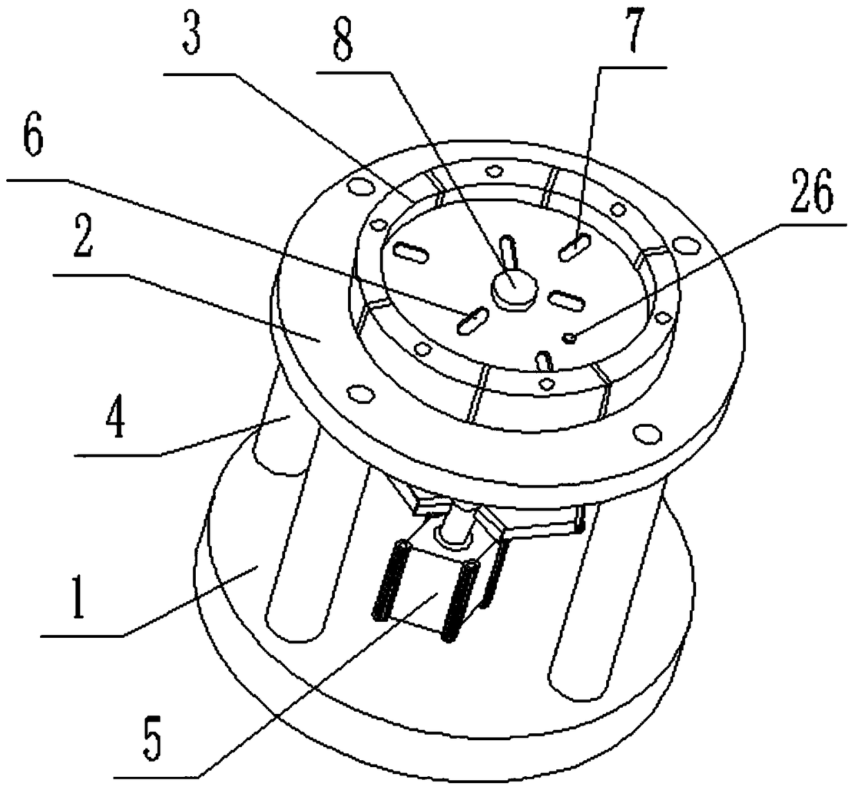
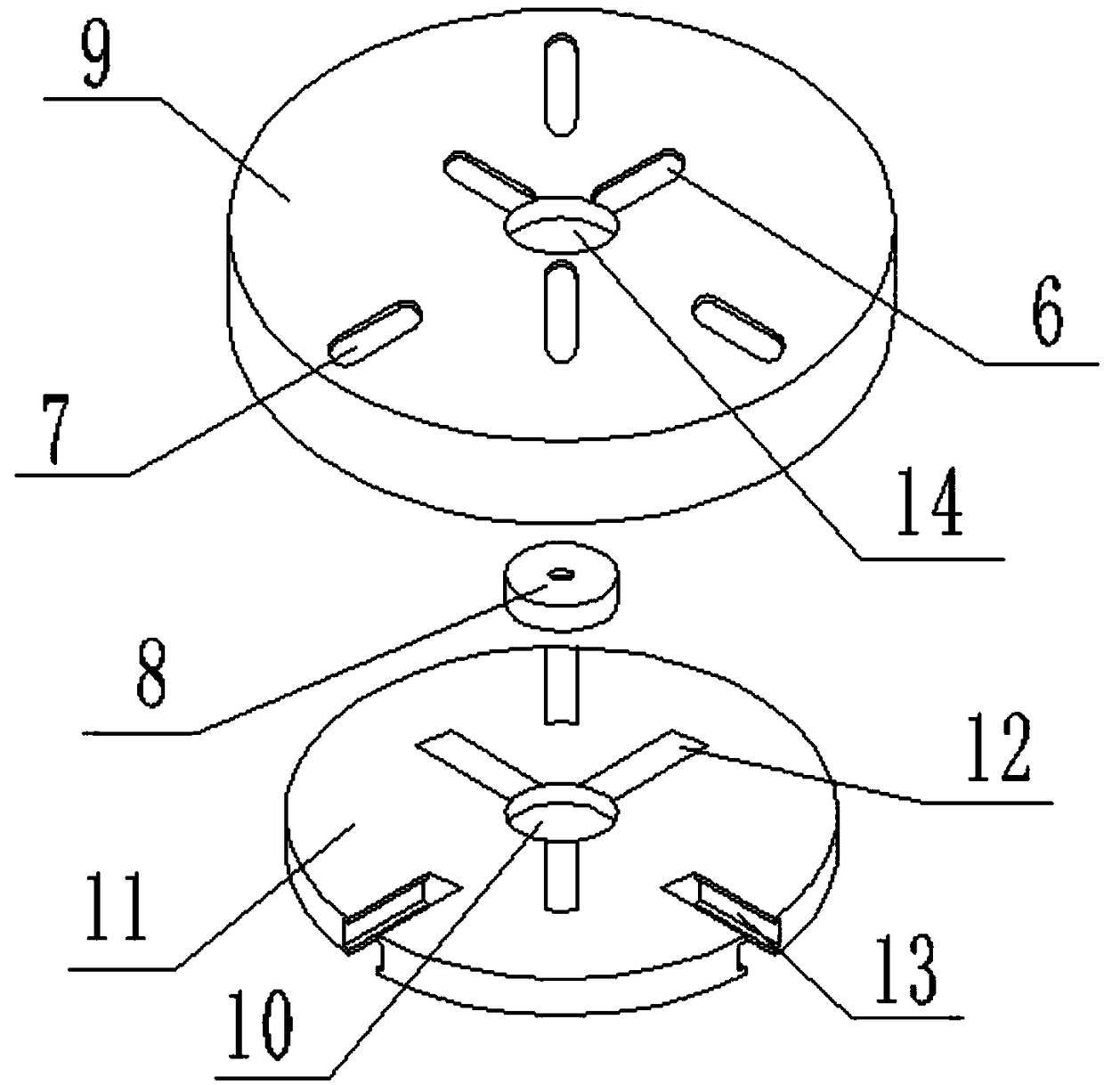
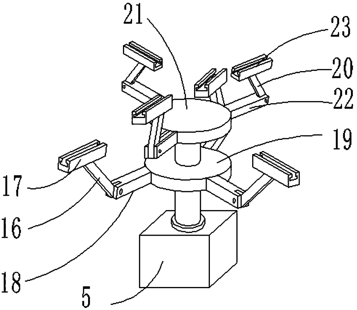
[0045] Such as Figures 1 to 6 As shown, the fixture tooling for scroll milling includes expansion part, positioning part and execution part.

[0046] The expansion part includes a first reference seat 2, a second reference seat 1 and six clamping blocks 3; the first reference seat 2 and the second reference seat 1 are connected as a whole by four connecting rods 4 bolts. The middle part of the first reference seat 2 is provided with a second-order stepped hole. The outer bottoms of the six clamping blocks 3 are all provided with protrusions, and the protrusions are hingedly connected to the inside of the stepped holes of the first step. The cross-sections of the bottoms of the inner side walls of the six clamping blocks 3 are all arc-shaped, so that the inner structure can act on them to clamp the blank. The tops of the six clamping blocks 3 are connected with clamping blocks through 10mm hexagonal bolts, and the clamping blocks are provided with tooth patterns for clamping...

Embodiment 2

[0063] The difference with embodiment 1 is:

[0064] There are four claws, positioning plate grooves and positioning plate holes, which can also realize the clamping function of the scroll blank.

Embodiment 3

[0066] The difference with embodiment 2 is:

[0067] The number of claws, positioning plate grooves and positioning plate holes are all eight, which can also realize the clamping function of the scroll blank.


PUM


Abstract

The invention discloses a clamp tool for scroll plate milling and using method thereof and belongs to the technical field of milling fixture tooling. An expansion portion comprises a first reference seat, a second reference seat and clamping blocks. Workblank members are clamped by the clamping blocks; a positioning portion comprises claws, a first positioning pin and a second positioning pin forpositioning; a first positioning plate comprises first positioning plate grooves and second positioning plate grooves, the first positioning plate grooves and second positioning plate grooves are alternately arranged at equal interval; the second positioning plate comprises first positioning plate holes and second positioning plate holes, the first positioning plate holes and second positioning plate holes are alternately arranged at equal interval; and the positions of the positioning plate grooves corresponds to the positions of positioning plate holes. The execution portion comprises an aircylinder, a first fixing plate, a second fixing plate and a link mechanism, the link mechanism is connected with the claws by a piston rod of the air cylinder, so that achieve the clamping from the bottom of the scroll plate, the influences of the cutting force and clamping force to the machining errors of machining surfaces are eliminated.

Description

technical field [0001] The invention belongs to the technical field of milling fixtures, and in particular relates to a scroll milling fixture and a usage method. Background technique [0002] The scroll compressor is a compressor with a compressible volume composed of a fixed involute scroll and an eccentric orbiting and translational involute moving scroll. The most important part is the scroll. The compressor has high requirements on the precision of the scroll. The machining error must be kept within a reasonable range in order to produce a qualified scroll. [0003] Most of the existing scroll milling fixtures use hydraulic, pneumatic or electric chucks, all of which only clamp the bottom of the scroll. This clamping method has disadvantages: when the tool is milling the scroll When the blank is turned, the tool will apply a large cutting force to the inner or outer wall of the scroll to cut the margin, and the blank will tend to move with the tool, and the chuck will ...

Claims


Application Information

Patent Timeline
Patent Type & Authority Applications(China)
IPC IPC(8): B23Q3/08
CPCB23Q3/062B23Q3/08B23Q2703/04Y02P70/10
Inventor 梁稳袁佳山徐波
Owner MAANSHAN AOTEJIA MECHANICAL & ELECTRICAL CO LTD
Why Eureka
Try Eureka