Pushing segmented hydraulic synchronous lifting assembling method for furnace shell of blast furnace

A hydraulic synchronous lifting and assembly method technology, which is applied to blast furnaces, blast furnace details, blast furnace parts, etc., can solve problems such as long shutdown time, large production impact, and large safety hazards

Inactive Publication Date: 2019-03-15
MCC TIANGONG GROUP
View PDF4 Cites 3 Cited by
  • Summary
  • Abstract
  • Description
  • Claims
  • Application Information

AI Technical Summary

Problems solved by technology

The volume of the blast furnace is also getting bigger and bigger, but the blast furnace body is continuously operated at high temperature, and the furnace body structure and equipment life are relatively short. The traditional method is generally to repair and replace the blast furnace in different parts, and some blast furnaces are moved offline to replace the furnace body structure, but the traditi

Method used


Image

  • Pushing segmented hydraulic synchronous lifting assembling method for furnace shell of blast furnace
  • Pushing segmented hydraulic synchronous lifting assembling method for furnace shell of blast furnace

Examples


Embodiment Construction

[0028] In order to further understand the content, characteristics and effects of the present invention, the following examples are given, and detailed descriptions are given below with reference to the accompanying drawings. It should be noted that this embodiment is descriptive, not restrictive, and cannot thereby limit the protection scope of the present invention.

[0029] A blast furnace shell pushing segmental hydraulic synchronous lifting assembly method, comprising the following steps:

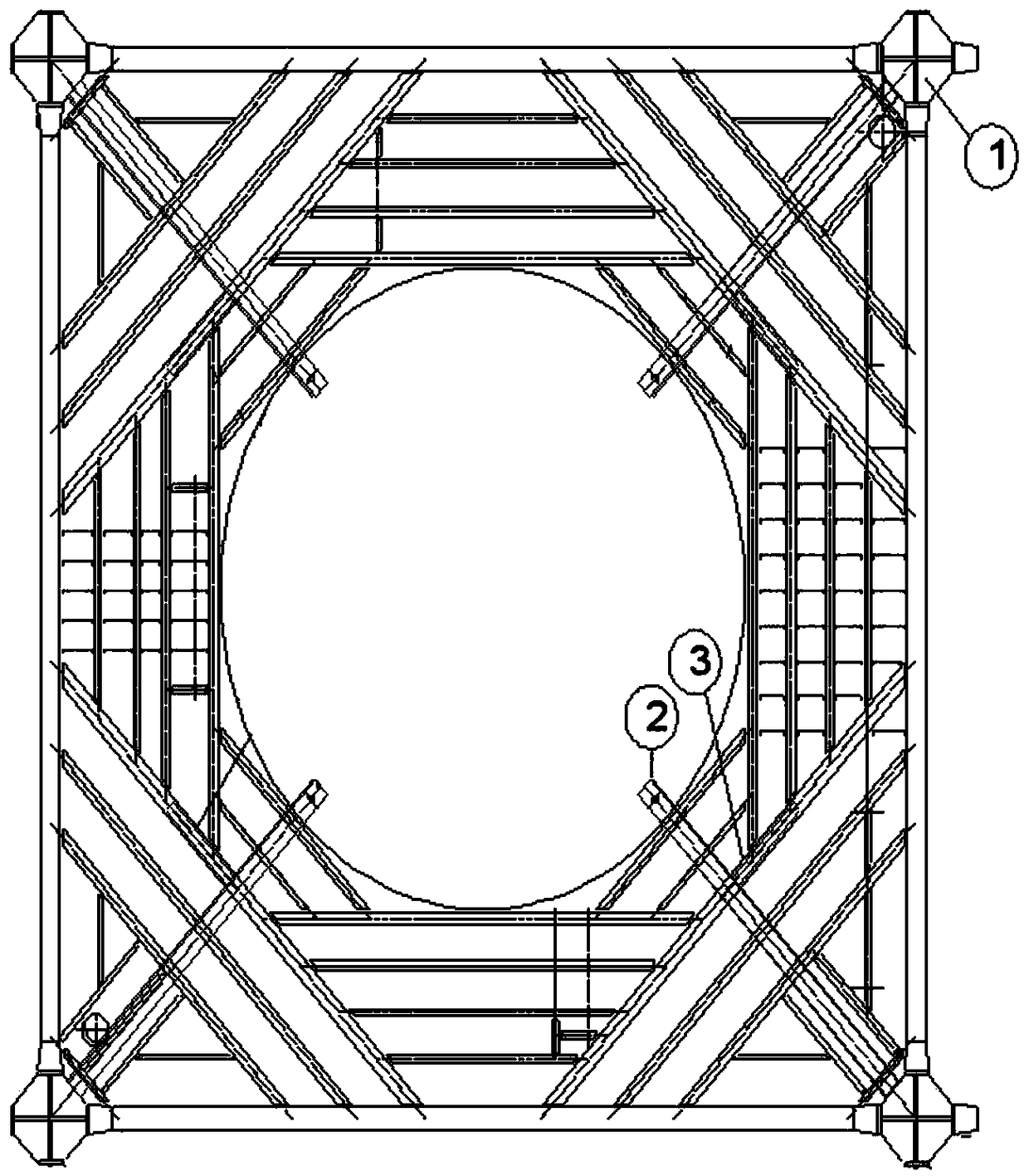
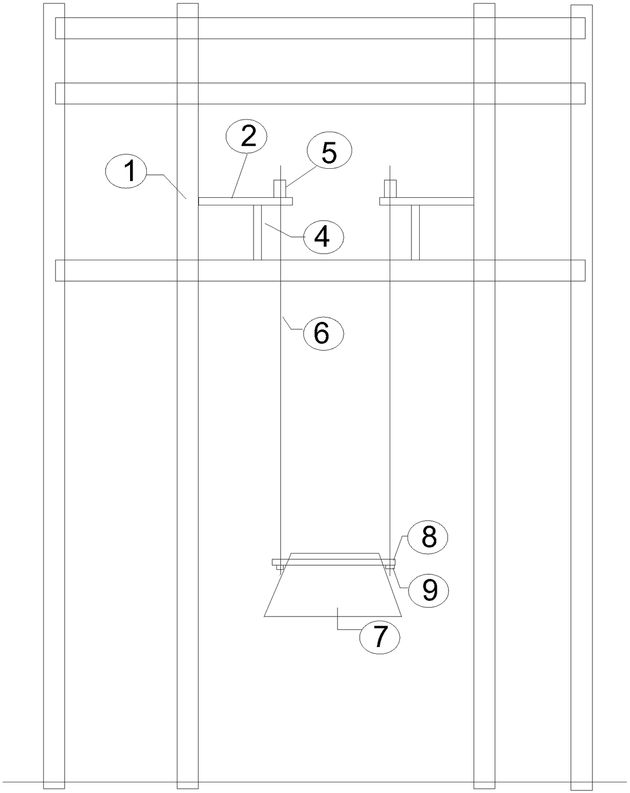
[0030] (1) On the four corner columns of the steel structure frame of the original old blast furnace body frame, the cantilevered steel beams of the hydraulic synchronous lifting system are welded horizontally. The cantilevered steel beams are made of H-shaped steel (HN700x300x13x24), and the cantilevered steel beams and the frame When welding the corner columns, the welding quality must be guaranteed, and the welding should be strengthened with stiffening plates; the length of the can...


PUM


Abstract

The patented technology is mainly used for achieving the problems that an industrial system blast furnace is pushed for replacement of a furnace body, when a blast furnace body structure is pushed forrapid replacement of the new furnace body, the structural stability of a blast furnace body framework structure is not affected to the largest degree, structure detachment is reduced for pushing thefurnace body, and the replacement time is saved. A method is suitable for overhauls and replacement of the furnace body structure of the high-capacity blast furnace, and the problems that the replacement period of the furnace shell of the blast furnace is long, and the idling period is long are solved.

Description

technical field [0001] The invention relates to the technical field of blast furnace construction, in particular to a blast furnace shell pushing segmental hydraulic synchronous lifting assembly method. Background technique [0002] With the development of modern industry, equipment is developing toward large-scale, high-efficiency, and low-energy consumption. The volume of the blast furnace is also getting bigger and bigger, but the blast furnace body is continuously operated at high temperature, and the furnace body structure and equipment life are relatively short. The traditional method is generally to repair and replace the blast furnace in different parts, and some blast furnaces are moved offline to replace the furnace body structure, but the traditional replacement method has a long shutdown time and partial maintenance, which has a great impact on production. The method of moving and replacing the furnace body structure off-line needs to destroy part of the main bo...

Claims


Application Information

Patent Timeline
IPC IPC(8): C21B7/00
CPCC21B7/00
Inventor 隋新杨俊刚林会明杨光杨志刚
Owner MCC TIANGONG GROUP
Why Eureka
Try Eureka