Supercharge Your Innovation With Domain-Expert AI Agents!

Rotor type compressor for loading bearing structure between stator and rotor and bearing assembling method

A technology for loading bearings and bearing assembly, which is applied in the fields of bearing assembly and rotor compressors, and can solve problems such as lack of oil

Active Publication Date: 2019-03-15
SHANGHAI HITACHI ELECTRICAL APPLIANCES CO LTD
View PDF3 Cites 0 Cited by
  • Summary
  • Abstract
  • Description
  • Claims
  • Application Information

AI Technical Summary

Problems solved by technology

Furthermore, because the oil flushed by the exhaust to the wall of the casing is different from the vertical concentration and returns to the oil suction side of the pump body in time, there is also a risk of oil shortage

Method used


Image

  • Rotor type compressor for loading bearing structure between stator and rotor and bearing assembling method
  • Rotor type compressor for loading bearing structure between stator and rotor and bearing assembling method
  • Rotor type compressor for loading bearing structure between stator and rotor and bearing assembling method

Examples


Embodiment Construction

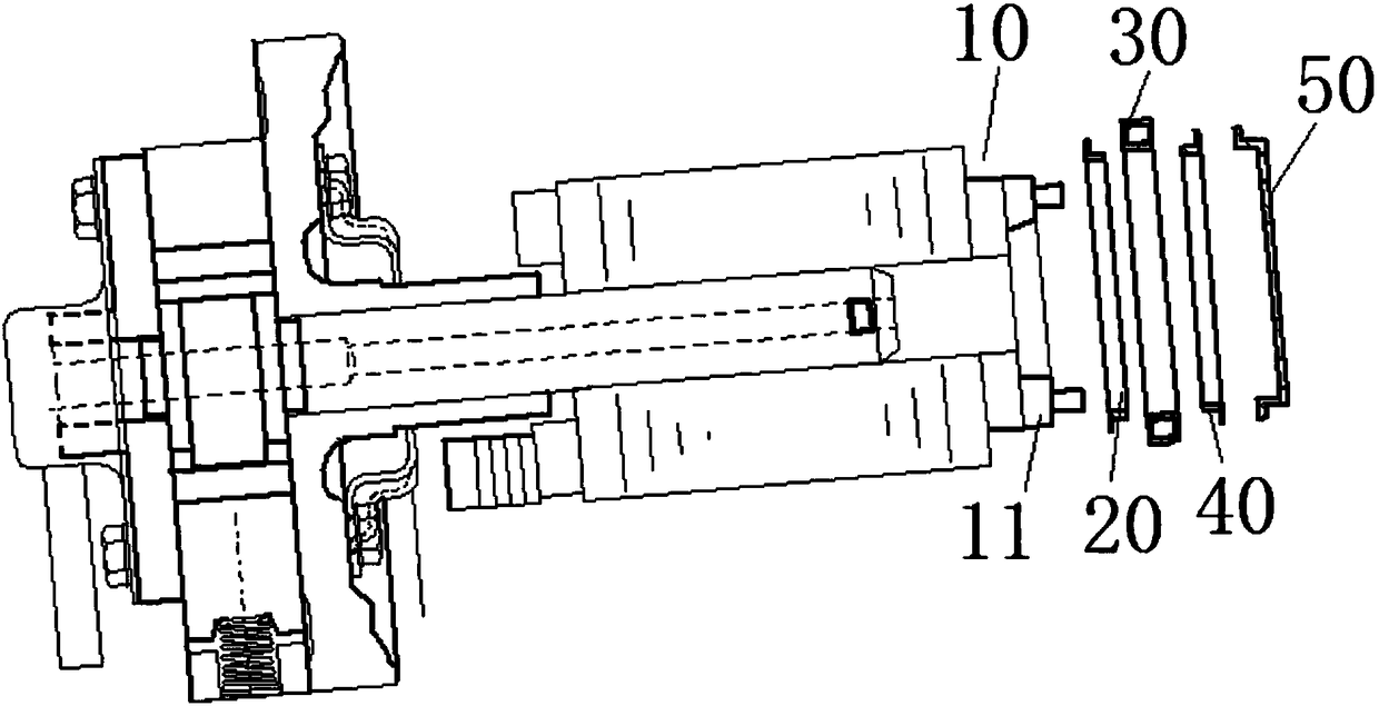
[0034] figure 2 It is an exploded schematic diagram of a rotor compressor with a loaded bearing structure between stator and rotor according to a preferred embodiment of the present invention.

[0035] Such as figure 2 As shown, according to the preferred embodiment of the present invention, the rotor-type compressor with the loading bearing structure between the stator and the rotor includes: the outer diameter groove 10 on the end surface of the rotor, the first snap ring 20 , the second snap ring 30 and the bearing 40 .

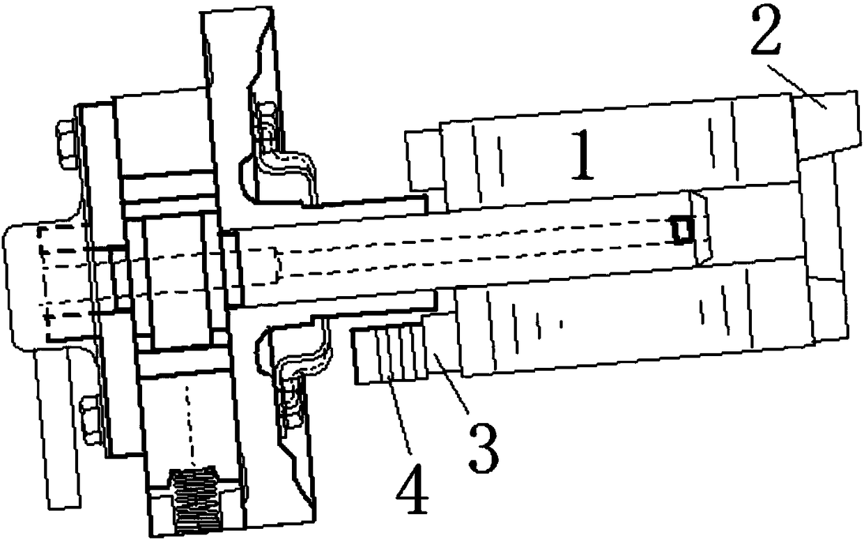
[0036] Specifically, for example, as figure 1 As shown, the rotor end surface outer diameter groove 10 is arranged on the rear side (vertical type) or the lower side (horizontal type) of the aluminum end ring 11 .

[0037] Wherein, the rotor end surface outer diameter groove 10 is arranged at the rotor end surface, and the first snap ring 20 and the second snap ring 30 are arranged side by side on the rotor end surface outer diameter groove 10 to form ...


PUM


Abstract

The invention discloses a rotor type compressor for loading a bearing structure between a stator and a rotor and a bearing assembling method. The rotor type compressor for loading the bearing structure between the stator and the rotor comprises a rotor end face outer diameter groove, a first clamp ring, a second clamp ring and a bearing, wherein the rotor end face outer diameter groove is formed in the end face of the rotor, and the first clamp ring and the second clamp ring are arranged on the rotor end face outer diameter groove side by side so as to form a groove to contain the bearing; andthe first clamp ring and the second clamp ring are made of insulation materials.

Description

technical field [0001] The invention relates to the field of compressor design, in particular to a rotor compressor with a loaded bearing structure between stator and rotor and a corresponding bearing assembly method. Background technique [0002] Existing rotary compressors, especially horizontal compressors, are gradually being used in vehicles and frequency conversion fields, and have higher requirements on the reliability of compressors. figure 1 A diagram of the existing structure is shown. Such as figure 1 As shown, the upper aluminum end of the rotor core 1 is provided with an integrated aluminum end ring and a combination 2 of balance weights, and the lower aluminum end of the rotor core 1 is provided with an aluminum end ring 3 and a rotor iron balance weight 4 . [0003] However, the force balance of the rotary horizontal compressor is still a difficult problem, mainly in several aspects: [0004] 1) The horizontal rotor is a cantilever beam structure, which is ...

Claims


Application Information

Patent Timeline
Patent Type & Authority Applications(China)
IPC IPC(8): F04C29/00F04D29/02F04D29/26F04D29/056B23P21/00
CPCB23P21/00F04C29/00F04D29/023F04D29/056F04D29/26F05C2251/00
Inventor 胡欣嘉李洁樊兆迪
Owner SHANGHAI HITACHI ELECTRICAL APPLIANCES CO LTD
Features
  • R&D
  • Intellectual Property
  • Life Sciences
  • Materials
  • Tech Scout
  • Unparalleled Data Quality
  • Higher Quality Content
  • 60% Fewer Hallucinations
Learn More