Treatment tool

A technology for treating instruments and masks, which is applied in the fields of heating surgical instruments, parts of surgical instruments, medical science, etc., can solve the problems of time-consuming and difficult to shorten the treatment time, and achieve the effect of low-invasive treatment and shortening the treatment time

Active Publication Date: 2019-03-15
OLYMPUS CORP
View PDF16 Cites 0 Cited by
  • Summary
  • Abstract
  • Description
  • Claims
  • Application Information

AI Technical Summary

Problems solved by technology

Therefore, there is a problem that it takes time to transmit heat in the thickness direction (grasping direction) of the tissue to be treated in the living tissue grasped by the first jaw and the second jaw, and it is difficult to shorten the treatment time.

Method used


Image

  • Treatment tool
  • Treatment tool
  • Treatment tool

Examples


Embodiment approach 1

[0026] [Outline structure of disposal system]

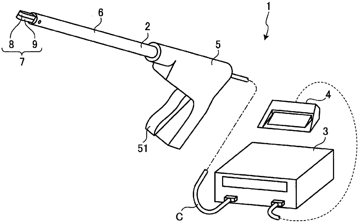
[0027] figure 1 It is a figure which shows the treatment system 1 which concerns on Embodiment 1 of this invention.

[0028] The treatment system 1 can treat living tissue (joint (or anastomosis) and resection, etc.) by applying energy (thermal energy and electric energy (high-frequency energy)) to the living tissue. Such as figure 1 As shown, the treatment system 1 includes a treatment instrument 2 , a control device 3 and a foot switch 4 .

[0029] [structure of disposal appliance]

[0030] The treatment instrument 2 is, for example, a linear surgical and medical treatment instrument for treating living tissue through the abdominal wall. Such as figure 1 As shown, the treatment instrument 2 includes a handle 5 , a rod part 6 and a grip 7 .

[0031] The handle 5 is a part where the operator holds the treatment tool 2 with his hand. Such as figure 1 As shown, the handle 5 is provided with an operating knob 51 .

[0032] ...

Embodiment approach 2

[0086] Next, Embodiment 2 of the present invention will be described.

[0087] In the description of Embodiment 2, the same reference numerals are assigned to the same configurations as in Embodiment 1 above, and detailed description thereof will be omitted or simplified.

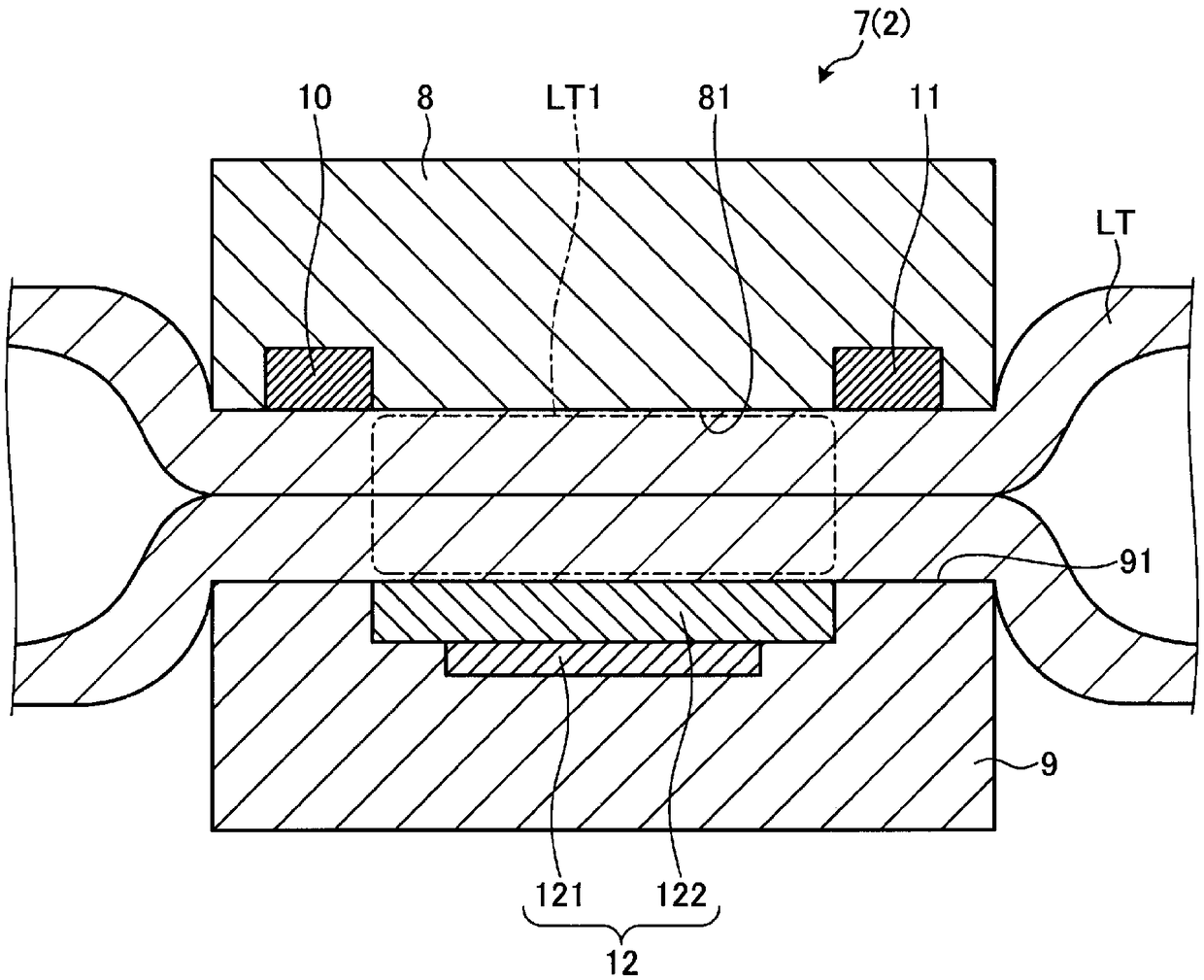
[0088] Figure 6 It is a figure which shows the grip part 7A which comprises the treatment instrument 2A which concerns on Embodiment 2 of this invention. in particular, Figure 6 With image 3 Corresponding sectional view.

[0089] In the treatment instrument 2A of the second embodiment, if Figure 6 As shown, with respect to the treatment instrument 2 described in Embodiment 1 above ( image 3 ), the setting positions of the first electrode and the second electrode of the present invention are different.

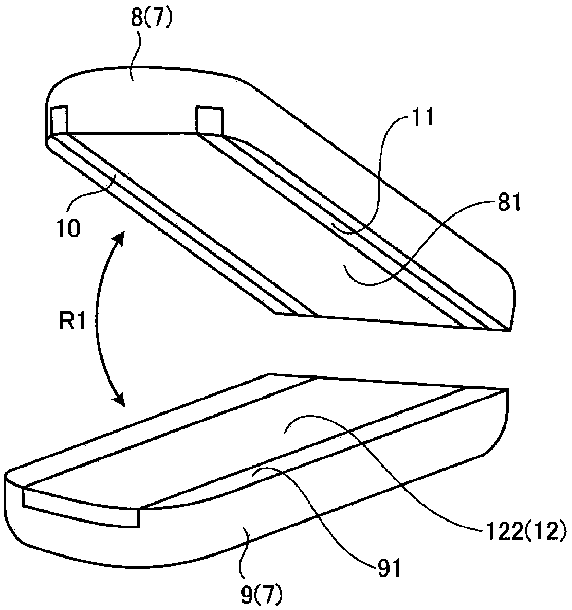
[0090] In one jaw 8 of Embodiment 2, on one gripping surface 81, such as Figure 6 As shown, the first and second electrodes 10, 11 are not provided. One gripping surface 81 of the second embodi...

Embodiment approach 3

[0100] Next, Embodiment 3 of the present invention will be described.

[0101] In the description of Embodiment 3, the same reference numerals are assigned to the same configurations as in Embodiment 1 above, and detailed description thereof will be omitted or simplified.

[0102] Figure 7 It is a figure which shows the grip part 7B which comprises the treatment instrument 2B in Embodiment 3 of this invention. in particular, Figure 7 With image 3 corresponding figure.

[0103] In the treatment instrument 2B of the third embodiment, if Figure 7 As shown, with respect to the treatment instrument 2 described in Embodiment 1 above ( image 3 ), the arrangement positions and formation methods of the first electrode and the second electrode of the present invention are different.

[0104] In one jaw 8 of Embodiment 3, as Figure 7 As shown, one gripping surface 81 has a flat shape without first and second electrodes 10 and 11 as in Embodiment 2 above. The non-adhesive in...


PUM


Abstract

This treatment tool is provided with: a first jaw (8) having a first holding surface (81); a second jaw (9) having a second holding surface (91) for holding a biotissue (LT) between the first holdingsurface (81) and the second holding surface; a first electrode (10) that is provided to the first holding surface (81); a second electrode (11), which is provided to the first holding surface (81) orthe second holding surface (91), and to which high frequency power is supplied between the first electrode (10) and the second electrode; and a heat generating body (121), which is provided to the first jaw (8) and / or the second jaw (9), and which generates heat when a current is carried thereto. In the state in which the first and second holding surfaces (81, 91) are facing each other, the firstand second electrodes (10, 11) are disposed at positions having the center position of the heat generating body (121) therebetween in the cases where the first and second electrodes are viewed in thefacing direction of the holding surfaces.

Description

technical field [0001] The present invention relates to treatment appliances. Background technique [0002] Conventionally, there is known a treatment tool capable of treating living tissue (joining (or anastomosis), excision, etc.) by applying energy to the living tissue (for example, refer to Patent Document 1). [0003] The treatment instrument (thermocoagulation incision forceps) disclosed in Patent Document 1 includes: a first jaw (first gripping portion) having a first gripping surface; and a second jaw (first gripping portion) having a second gripping surface. Two grasping parts), which can grasp the living tissue between the second grasping surface and the first grasping surface. A heating element is provided on the first jaw, which can generate heat due to energization to heat the first gripping surface. In this treatment instrument, the living tissue can be grasped by the first jaw and the second jaw, and the living tissue can be treated by heating the living tis...

Claims


Application Information

Patent Timeline
Patent Type & Authority Applications(China)
IPC IPC(8): A61B18/12A61B18/08
CPCA61B18/08A61B18/12A61B18/1445A61B18/085A61B2018/00607A61B2018/0063A61B2018/00589A61B2018/00994A61B18/1206A61B18/1482
Inventor 鹤田尚英
Owner OLYMPUS CORP
Why Eureka
Try Eureka