Reciprocatory dry shaver

A technology of reciprocating motion and motion device, which is applied in the direction of AC motor control, metal processing, electrical components, etc., and can solve problems such as vibration frequency change, speed slowdown, unbalanced vibration of the shaver head, etc.

Inactive Publication Date: 2002-11-27
MATSUSHITA ELECTRIC WORKS LTD
View PDF7 Cites 2 Cited by
  • Summary
  • Abstract
  • Description
  • Claims
  • Application Information

AI Technical Summary

Problems solved by technology

[0005] However, in a shaver that uses a plurality of reciprocators to drive a plurality of moving blades in order to increase the area to be shaved simultaneously, when one

Method used


Image

  • Reciprocatory dry shaver
  • Reciprocatory dry shaver
  • Reciprocatory dry shaver

Examples


Embodiment 1

[0029] Example 1 ( Figure 1-12 )

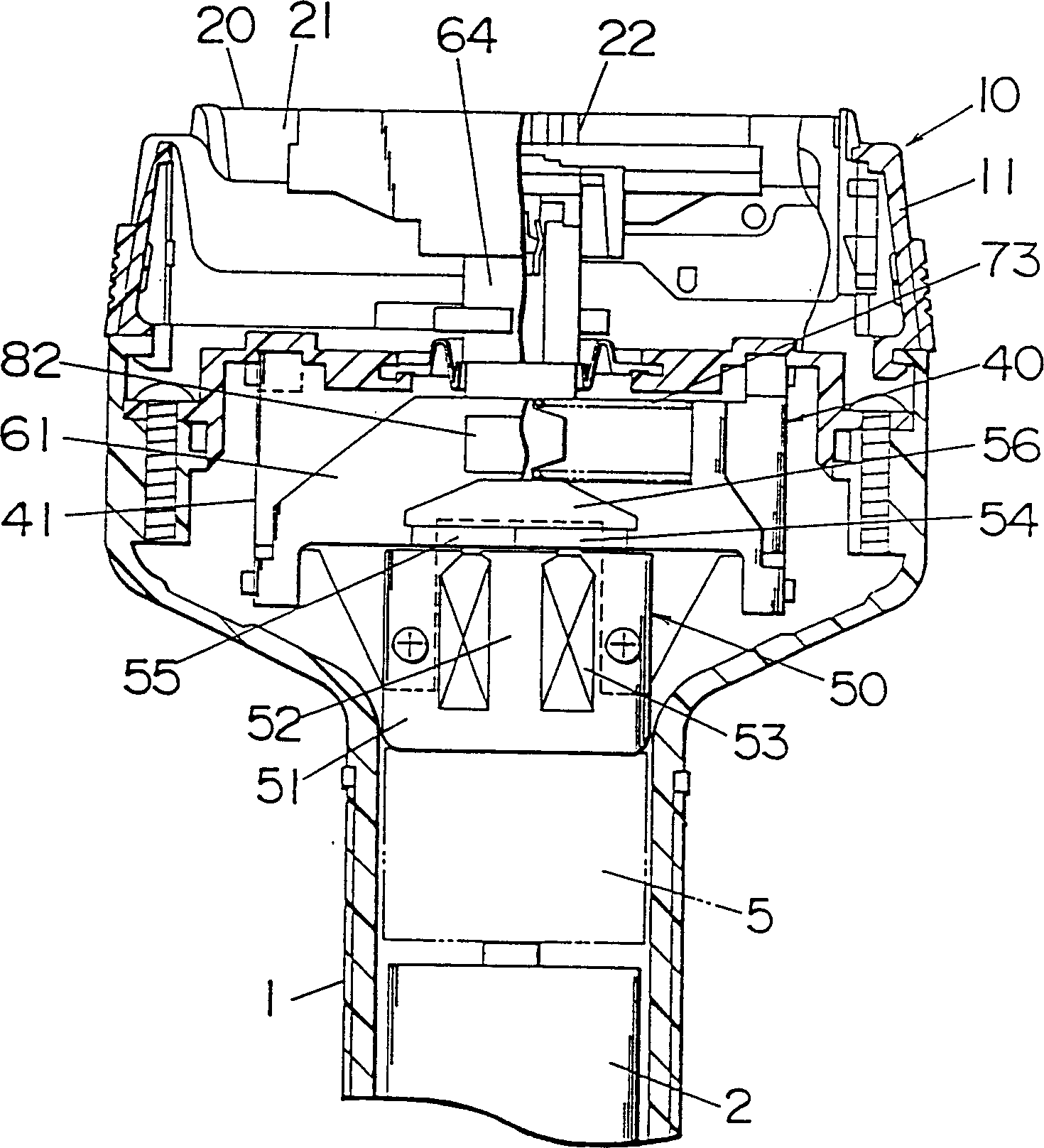
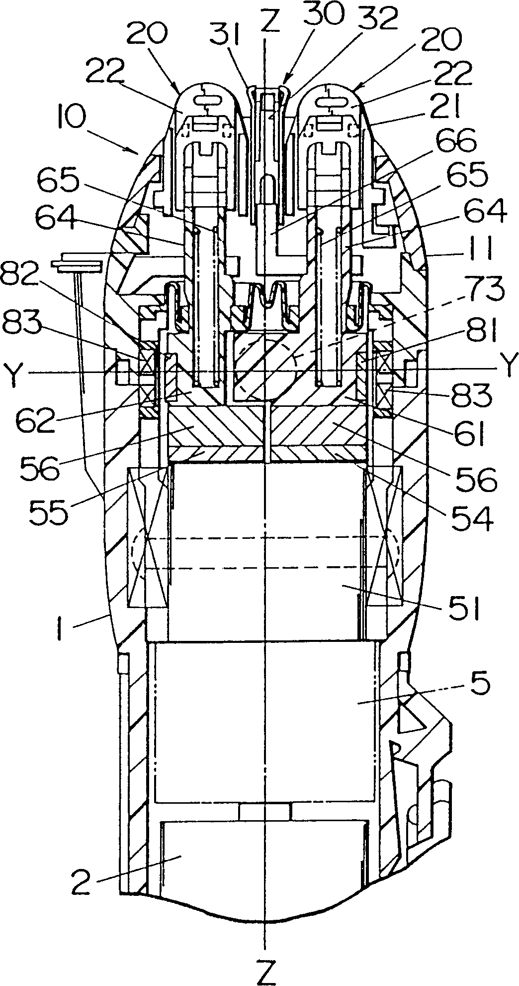
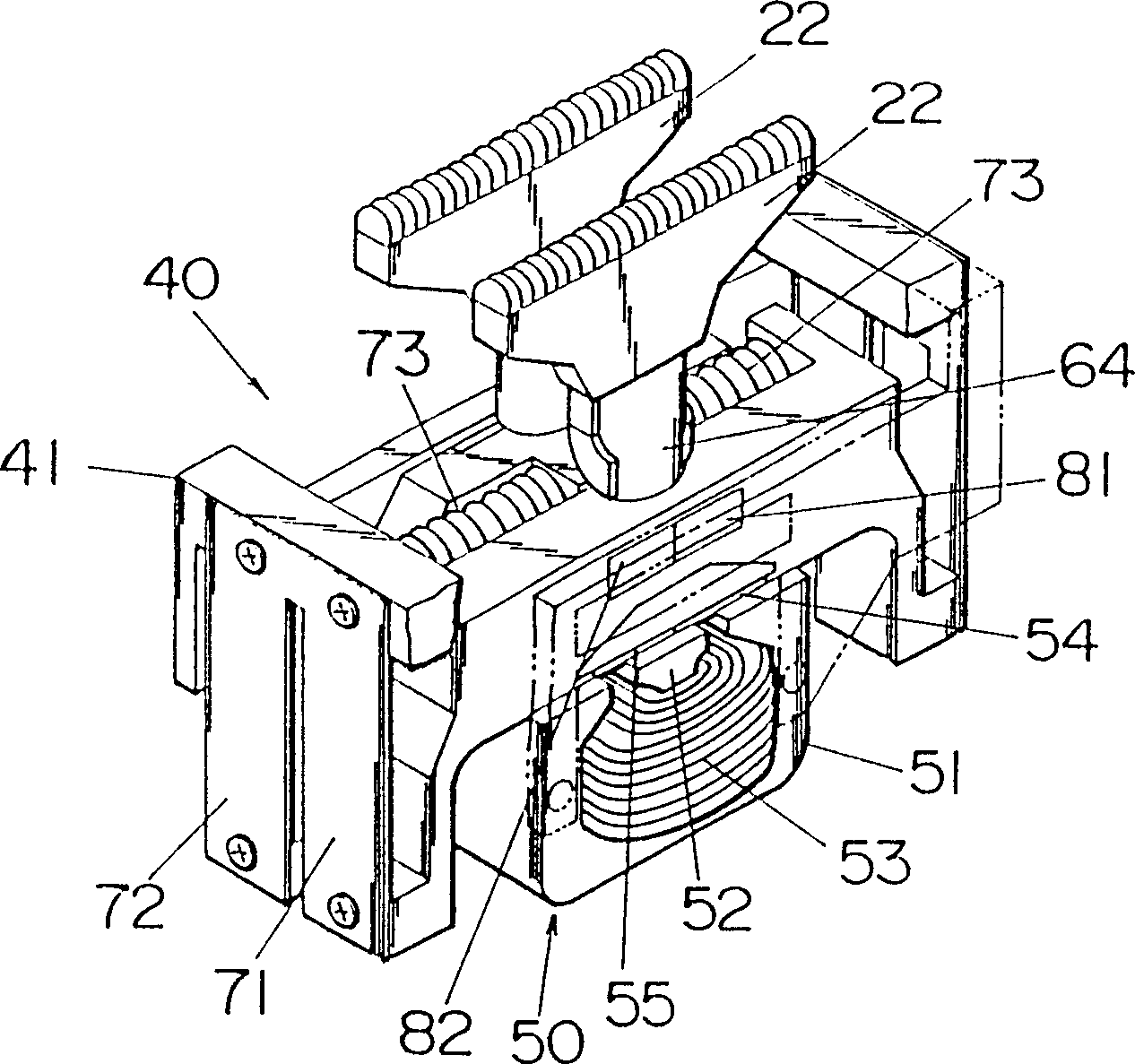
[0030] refer to Figure 1-Figure 5 , which represents the reciprocating type dry shaver of the first embodiment of the present invention. This shaver comprises shell 1 with shaver head 10, is provided with two outer blade heads 20 and a middle blade head 30 on the shaver head, middle blade head 30 and outer blade head 20 extend horizontally parallel to each other . The outer blade head 20 includes a stationary blade 21 whose cutting piece is generally U-shaped in cross-section and a moving blade 22 that is driven to reciprocate and contacts the stationary blade 21 during cutting. The stationary blade 21 is installed on the head frame 11, and the head frame is detachably mounted on the shell 1, and the movable blade 22 is mounted on the blade holder 40 in the shell 1 at the same time. The middle blade head 30 includes a generally U-shaped serrated blade 31 and a movable blade 32 driven to reciprocate and contact the blade 31 during cuttin...

Embodiment 2

[0051] Example 2 ( Figure 13-16 )

[0052] Figure 13-16 Showing the dry shaver according to the second embodiment of the present invention, the structure is the same as that of the first embodiment except that reciprocators 61A and 62A of different shapes are used. The same components as above are denoted by the same reference numerals with a subscript "A" and their description will not be repeated here. The reciprocator 62A in the form of a rectangular frame comprises two parallel elements 162 connected by end bars 161 , while the reciprocator 61A comprises an elongated element disposed between the elements 162 . Extending from a member 162 of the reciprocator 62A is an engagement portion 64A for mounting the movable blade 22A corresponding to the outer blade head 20A. The other reciprocator 61A has an engaging portion 64A protruding from an intermediate protrusion 68A for coupling with the movable blade 22A holding the blade head 20A. A part 66A coupled with the moving...

Embodiment 3

[0066] Embodiment 3 ( Figure 17 and 18 )

[0067] Figure 17 Shown is a blade holder 40B employed in the dry shaver according to the third embodiment of the present invention. The blade holder 40B is the same as the blade head 40 in the first embodiment except that one coil spring 73B is shared among the two vibration systems of the reciprocators 61B and 62B. Like parts are denoted by like reference numerals with a subscript "B". In this example, as Figure 18 As shown, inwardly protruding end projections 67B are formed on the reciprocators 61B and 62B, respectively, and a coil spring 73B is provided between the projections 67B. The coil spring 73B has a spring constant which, when added to the horizontal components of the leaf springs 71B, 72B and the motor, provides force constants K1 and K2 suitable for both vibration systems.


PUM


Abstract

A reciprocatory dry shaver comprises a stationary cutter (21), a movable cutter (22), and a permanent-magnet linear motor (50) having a stator (51) and a reciprocator (61,62) which is driven by an electric current to reciprocate relative to the stator (51). The reciprocator (61,62) carries the movable cutter (22) to reciprocate it in shearing engagement with the stationary cutter (21). A power circuit (2) is included to provided an electric power to the motor (50). The shaver includes a detector (83) which detects a displacement of the movable cutter (22) and give an output indicative of the detected displacement of the movable cutter (22). Also included in the shaver is a controller (100) which varies the electric power being fed to the motor (50) in a feedback manner based upon the output from the speed detector (83) in order to keep an oscillation amplitude of the movable cutter (22) at constant. In this manner, the movable cutter (22) can reciprocate without being jammed even when experiencing a heavy load during the shaving, thereby avoiding undesired speed reduction of the movable cutter (22) which would result in the lowering of the cutting efficiency. Thus, the reciprocatory dry shaver is capable of keeping a constant oscillation amplitude irrespective of a load acting on a movable cutter (22) to thereby assure a sharp cut even when the movable cutter experiences a heavy load during the shaving. <IMAGE>

Description

[0001] The present invention is a divisional application of Chinese patent application No. 95 1 90233.4. technical field [0002] The invention relates to a reciprocating dry shaver, which includes a reciprocating moving blade driven by a permanent magnet linear motor. Background technique [0003] European Patent Publication EP349077 describes a reciprocating dry shaver comprising a linear motor that reciprocates a moving blade and engages a stationary blade while clipping. The motor includes an electromagnet as a stator and a permanent magnet as a reciprocator supporting the moving blade. The electromagnet is energized by a fixed frequency current to drive the reciprocator and the moving blade. During shaving, when the moving blade is subjected to a gravity load, the moving blade is only moved by a slight impact, which will reduce the speed of the moving blade while reducing the vibration amplitude, thereby reducing the sharpness of the shave and even leaving uncut edges....

Claims


Application Information

Patent Timeline
IPC IPC(8): B26B19/28H02K33/10H02P25/02
CPCB26B19/282H02K33/10H02P25/032
Inventor 本桥良棚桥正雄木村六三郎
Owner MATSUSHITA ELECTRIC WORKS LTD
Why Eureka
Try Eureka