Permanent magnet governor with lever air gap adjustment device

A technology for permanent magnet speed governors and regulating devices, which is applied in the direction of electromechanical devices, electromechanical transmission devices, electrical components, etc., can solve problems such as difficult manufacturing, excessive wear, and difficult manufacturing of push-pull mechanisms, and achieve accurate and stable gas Gap adjustment, vibration and noise reduction, easy inspection and maintenance effects

Active Publication Date: 2018-11-27
MAGNA MAGNETOMOTIVE CO LTD
View PDF7 Cites 0 Cited by
  • Summary
  • Abstract
  • Description
  • Claims
  • Application Information

AI Technical Summary

Problems solved by technology

The cams and cam grooves between the inner and outer cylinders, the cam grooves of the rocker arm and the rollers must be coordinated. It is difficult to coordinate the movement, and it is easy to cause local excessive wear, jamming or even damage to parts.
[0007] 2. High manufacturing cost
Therefore, the manufacturing cost of this push-pull mechanism is higher
[0008] 3. It is difficult to manufacture
Therefore, this push-pull mechanism is not easy to manufacture

Method used


Image

  • Permanent magnet governor with lever air gap adjustment device
  • Permanent magnet governor with lever air gap adjustment device
  • Permanent magnet governor with lever air gap adjustment device

Examples


Embodiment Construction

[0031] The specific embodiment of the present invention will be further described below in conjunction with accompanying drawing:

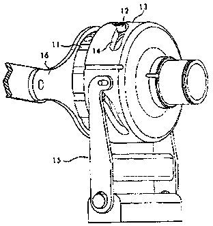
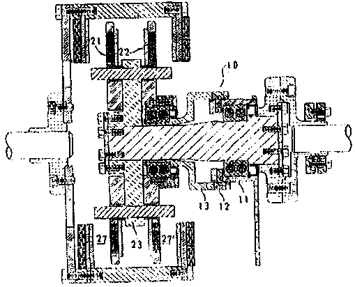
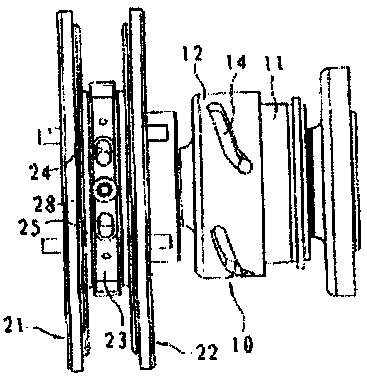
[0032] See Figure 5 , Figure 6 , is a structural schematic diagram of an embodiment of a permanent magnet governor with a lever-type air gap adjustment device in the present invention, including a conductor rotor 1, a permanent magnet rotor 2, an intermediate shaft 3 and an air gap adjustment mechanism, and the conductor rotor 1 is in phase with the conductor side hub 4 Connection, the air gap adjustment mechanism includes a linear driver 5, a lever 6 and an adjustment sleeve 7, the adjustment sleeve 7 is connected with the permanent magnet rotor 2 through the permanent magnet side hub 8, the permanent magnet side hub 8 is slidingly connected with the intermediate shaft 3, and the intermediate shaft 3 One end of the driving rod 6 is connected to the middle disc 9; one end of the driving rod 6 is a U-shaped opening, which is hinged with the oute...


PUM


Abstract

The invention relates to the technical field of permanent magnet speed adjustment, in particular to a permanent magnet governor with a shift lever-type air gap adjusting device. The permanent magnet governor comprises a conductor rotor, a permanent magnet rotor, an intermediate shaft and an air gap adjusting mechanism. The permanent magnet governor is characterized in that the air gap adjusting mechanism comprises a linear driver, a shaft lever and an adjusting sleeve; the adjusting sleeve is connected with the permanent magnet rotor through a permanent magnet side hub; the permanent magnet side hub is connected with the intermediate shaft in a sliding manner; one end of the intermediate shaft is connected with an intermediate plate; a U-shaped opening is formed in one end of the shaft lever; one end of the shaft lever is hinged with the outer wall of the adjusting sleeve; the middle point of the shaft lever is hinged with the end part of a support rod; the support rod is fixed on a support base; and the other end of the shaft lever is hinged with a piston end of the linear driver. Compared with the prior art, the permanent magnet governor has the beneficial effects that, compared with an existing inner and outer barrel cam structure, the permanent magnet governor has the characteristics of a large arm of acting force and an external maximum stress point; enough acting force can be generated to balance vibration of the magnet rotor; a damageable part is easier to inspect and maintain; and the permanent magnet governor has relatively high safety and reliability.

Description

technical field [0001] The invention relates to the technical field of permanent magnet speed regulation, in particular to a permanent magnet speed governor with a lever type air gap adjusting device. Background technique [0002] The invention patent ZL98802726.7 proposed by Magnaforth Corporation of the United States on February 20, 1998 discloses a permanent magnet governor, its structure is as follows: figure 1 , mainly composed of copper rotor, magnetic rotor and air gap adjustment device. Installed between the prime mover and the load machine, according to the needs of the load machine operation, the air gap between the copper rotor and the magnetic rotor can be adjusted through the air gap adjustment device to change the speed of the load machine, while the motor keeps a constant speed. . [0003] The air gap adjusting device of the permanent magnet governor includes two push-pull mechanisms. The first push-pull mechanism (see Figure 1-2 ) 10 is a cylindrical cam...

Claims


Application Information

Patent Timeline
Patent Type & Authority Patents(China)
IPC IPC(8): H02K51/00
Inventor 马忠威
Owner MAGNA MAGNETOMOTIVE CO LTD
Why Eureka
Try Eureka