A piston type nut locking device

A nut locking and piston-type technology, which is applied in metal processing equipment, metal processing, manufacturing tools, etc., can solve the problems of long time-consuming installation of nuts, narrow space of the main board, and suffering of operators, so as to shorten the assembly time and be universal. Good performance and reduce the difficulty of assembly

Active Publication Date: 2020-11-03
NINGBO HAIMAIKE AUTOMATION TECH CO LTD
View PDF6 Cites 0 Cited by
  • Summary
  • Abstract
  • Description
  • Claims
  • Application Information

AI Technical Summary

Problems solved by technology

However, the space at the four corners of the main board is extremely narrow. At present, the nuts can only be placed manually, and then tightened with an extended T-type wrench. It takes a long time to install the nut on the long screw rod and the operation is difficult, which is almost a kind of torture for the operator

Method used


Image

  • A piston type nut locking device
  • A piston type nut locking device

Examples


Embodiment 1

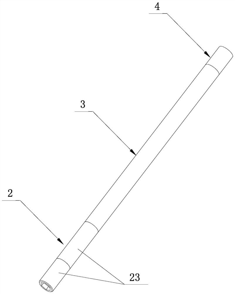
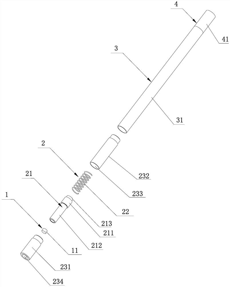
[0021] A piston type nut locking device proposed in this embodiment, as shown in the figure, includes a nut absorbing part 1 for absorbing a hex nut to prevent it from falling, The piston part 2 which is in a compressed state under the action of upward push, the extension rod part 3 used to lengthen the overall length according to the installation environment of the hex nut, the joint part 4 used to connect external electric tools or external pneumatic tools, and the piston part 2 drives when it moves The nut adsorption part 1 moves together; when installing the hexagonal nut, align the hexagonal nut absorbed by the nut adsorption part 1 with the screw and put it down. , start the external electric tool or external pneumatic tool, the power output by the external electric tool or external pneumatic tool drives the piston nut locking device to rotate through the joint part 4, the hexagonal nut absorbed by the nut adsorption part 1 is screwed into the screw rod, and the The pist...

Embodiment 2

[0025] A kind of piston type nut locking device proposed in this embodiment, its structure is basically the same as that of the piston type nut locking device in Embodiment 1, the only difference is: figure 1 and figure 2 The extension rod part 3 in the middle is made up of a group of connecting rods of different lengths, and each connecting rod is used separately, the front end of the connecting rod is fixedly connected with the rear end of the rear sleeve 232, and the rear end of the connecting rod is connected with the front end of the joint sleeve 41 Fixed connection; since the length of each connection in a set of connecting rods varies, several different lengths of connecting rods can be designed according to different nut installation environments.

Embodiment 3

[0027] The structure of the piston-type nut locking device proposed in this embodiment is basically the same as that of the piston-type nut locking device in Embodiment 2, the only difference being: figure 1 and figure 2 The extension rod part 3 in the middle is made up of a group of connecting rods of different lengths, and a plurality of connecting rods are connected end to end to be used as a whole. The end is fixedly connected with the joint part 4; because the lengths of a group of connecting rods are different, and the end-to-end connection of multiple connecting rods has a variety of combinations of different lengths, the piston nut locking device can be adapted to all occasions with different depths nut installation.

[0028] As mentioned above, in the piston-type nut locking devices given in Embodiment 2 and Embodiment 3, all connecting rods are connected in the same way, so that they can be combined at will, and the front end of any connecting rod can be connected ...


PUM


Abstract

The invention discloses a piston type nut locking device. The piston type nut locking device comprises a nut absorbing part, a piston part, a lengthening rod part, and a connector part used for beingconnected with an external electric / pneumatic tool. The piston part drives the nut absorbing part to move when moving. During mounting, the nut absorbing part attracts a hex nut to align a screw for penetrating. The piston part is in the original state at this moment. The hex nut is jacked onto the screw, the external electric / pneumatic tool is started to drive the piston type nut locking device to rotate. The hex nut is screwed into the screw, the top of the screw jacks upwards, and the piston part is in the compression state. When the hex nut is locked, a clutch of the external electric / pneumatic tool is separated and turned off, so that the piston type nut locking device is separated from the screw, and the piston part reverts to the original state. The piston type nut locking device has the advantages that the assembling time is shortened, assembling efficiency is improved, assembling difficulty is lowered, and the piston type nut locking device is suitable for mounting nuts in mounting environments with different mounting depths.

Description

technical field [0001] The invention relates to a nut installation device, in particular to a piston-type nut locking device, which is suitable for installation of nuts on a longer center screw rod, such as installing nuts on a long screw rod that fixes a main substrate inside an electric control box . Background technique [0002] At present, there are a relatively large number of electric control boxes on the market, and the main substrate inside is usually fixed by welding long screws and locking with nuts. Generally, in the process of fixing the main substrate, the electrical components are first installed on the main substrate, the long screws are welded to the four corners of the main substrate, and then the main substrate is sunk into the inside of the electric control box, and then locked with nuts. However, the space at the four corners of the main board is extremely narrow. At present, the nuts can only be placed manually, and then tightened with an extended T-typ...

Claims


Application Information

Patent Timeline
Patent Type & Authority Patents(China)
IPC IPC(8): B23P19/06
CPCB23P19/06
Inventor 阮光敏肖斌童栗炜黄文强施洁洁童焕强蒋磊谢科杰吴敏迪郭奕含杜宁达
Owner NINGBO HAIMAIKE AUTOMATION TECH CO LTD
Why Eureka
Try Eureka