Constant-speed mixing equipment for producing nylon 6 injection molding slices and production method of nylon 6 injection molding slices

A technology of mixing equipment and production method, which is applied in the field of mixing equipment modified by nylon 6 slices, can solve the problems of easy concentration and falling directly below the discharge port, troublesome collection of nylon 6 injection molding slices, and slow drying speed, etc., to achieve Ensure highly dispersed mixing, ensure particle integrity, and prevent contamination

Pending Publication Date: 2019-03-19
JIANGSU HAIYANG CHEM FIBERS
View PDF0 Cites 1 Cited by
  • Summary
  • Abstract
  • Description
  • Claims
  • Application Information

AI Technical Summary

Problems solved by technology

[0004] The purpose of the present invention is to provide a uniform mixing equipment for the production of nylon 6 injection molding slices, to solve the problem that the drying part of the general nylon 6 slice production equipment proposed in the above background technology needs to consume a lot of energy, and the drying speed is relatively slow Secondly, the collection of nylon 6 injection-molded slices in general nylon 6 slice production equipment is more troublesome, and nylon 6 injection-...

Method used


Image

  • Constant-speed mixing equipment for producing nylon 6 injection molding slices and production method of nylon 6 injection molding slices
  • Constant-speed mixing equipment for producing nylon 6 injection molding slices and production method of nylon 6 injection molding slices
  • Constant-speed mixing equipment for producing nylon 6 injection molding slices and production method of nylon 6 injection molding slices

Examples


Embodiment 1

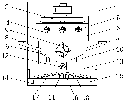
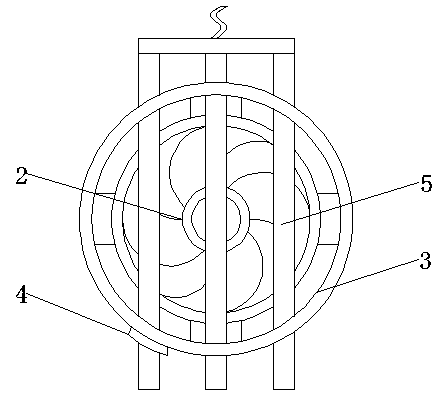
[0030] see Figure 1-3 , the present invention provides a technical solution: a uniform mixing equipment for the production of nylon 6 injection molding slices, including a casing 1, a stirring box 6 and a movable box 16, a fan 2 is installed inside the casing 1, and the lower edge of the fan 2 A baffle 3 is welded, the surface of the baffle 3 is provided with a circular groove 4, and the interior of the circular groove 4 runs through a baking lamp 5, the baffle 3 is connected with the baking lamp 5 through the circular groove 4, and the baking The lamps 5 are evenly distributed along the horizontal direction of the fan 2, and the baking lamps 5 are parallel to each other. The position is fixed, so that the baking lamp 5 is suspended and fixed under the fan 2, and the fan 2 can directly diffuse the heat emitted by the baking lamp 5 downwards in the working state, so that the heat emitted by the baking lamp 5 The heat falls on the nylon 6 slices quickly and accurately, which s...

Embodiment 2

[0034] A method for producing nylon 6 injection-molded slices, using the above-mentioned constant speed mixing equipment, the specific steps are as follows: both ends of the baking lamp 5 are inserted into the inside of the circular groove 4, and the two ends of the baking lamp 5 are heated through the circular groove 4. Fix the position, so that the baking lamp 5 is suspended and fixed under the fan 2, and the nylon 6 slices are injected into the inside of the mixing box 6 through the first feeding pipe 7, and then it is baked by the baking lamp 5 and the fan 2 Dry operation, after the drying of the nylon 6 slices, the white oil is injected into the inside of the stirring box 6 through the second feed pipe 8, and the white oil and the nylon 6 slices are mixed at a low speed for 10 minutes through the stirring mechanism 9, because the nylon 6 slices It is a solid structure, so when the nylon 6 slices pass through the first feeding pipe 7, it is not easy to remain on the inner w...

Embodiment 3

[0040] A method for producing nylon 6 injection-molded slices, using the above-mentioned constant speed mixing equipment, the specific steps are as follows: both ends of the baking lamp 5 are inserted into the inside of the circular groove 4, and the two ends of the baking lamp 5 are heated through the circular groove 4. Fix the position, so that the baking lamp 5 is suspended and fixed under the fan 2, and the nylon 6 slices are injected into the inside of the mixing box 6 through the first feeding pipe 7, and then it is baked by the baking lamp 5 and the fan 2 Dry operation, after the drying of the nylon 6 slices, the white oil is injected into the inside of the stirring box 6 through the second feed pipe 8, and the white oil and the nylon 6 slices are mixed at a low speed for 10 minutes through the stirring mechanism 9, because the nylon 6 slices It is a solid structure, so when the nylon 6 slices pass through the first feeding pipe 7, it is not easy to remain on the inner w...


PUM


Abstract

The invention discloses constant-speed mixing equipment for producing nylon 6 injection molding slices and a production method of the nylon 6 injection molding slices. The constant-speed mixing equipment comprises an outer shell, a stirring box and a movable box, a draught fan is installed in the outer shell, and a circular groove is formed in the surface of a sideboard. A first feeding pipe is arranged on the right side surface of the stirring box, a second feeding pipe is installed on the right side surface of the stirring box, a first slope is arranged below a stirring mechanism, a valve isfixedly installed on the surface of a discharging opening, the lower surface of the stirring box is welded to the upper surface of a saddle, a sliding groove is formed in the lower surface of the interior of the outer shell, and a second slope is integrally installed in the movable box. According to the constant-speed mixing equipment for producing the nylon 6 injection molding slices, the loss of energy can be reduced, and the collection of the injection molding slices is more convenient; and meanwhile, the injection molding slices produced by using the constant-speed mixing equipment have better performance.

Description

technical field [0001] The invention relates to the technical field of mixing equipment for modification of nylon 6 slices, in particular to a uniform mixing equipment and production method for producing nylon 6 injection-molded slices. Background technique [0002] Nylon 6 slices are also known as nylon 6 slices, the CAS number is 25038-54-4, and the molecular formula is -[NH(CH2)5CO]-n. It is soluble in phenol and hot concentrated sulfuric acid. It has excellent electrical insulation performance, alkali resistance, It has good corrosion resistance and is the fiber with the best wear resistance among synthetic fibers. When nylon 6 chips are directly used in the injection molding industry, there are the following problems: ① Long molding cycle, ② Difficult to demould, ③ High energy consumption, ④ Low production efficiency . To solve similar problems, the general method is to add nylon-specific functional additives. When manufacturers add them by themselves, there will be a ...

Claims


Application Information

Patent Timeline
IPC IPC(8): B29B7/16B29B7/24B29B7/26B29B7/22B29B13/06
CPCB29B7/16B29B7/22B29B7/24B29B7/26B29B13/06
Inventor 吉增明李小吉严栋陈海玲
Owner JIANGSU HAIYANG CHEM FIBERS
Why Eureka
Try Eureka