Chain feeding device

A chain and sprocket technology, which is applied in the direction of transportation and packaging, conveyors, conveyor objects, etc., can solve the problems of deviation from the actual needs of the automatic feeding device in the factory, the structure of the feeding device is complicated, and the economic cost is high, so as to facilitate widespread promotion The effect of using, fewer transmission stages, and low economic cost

Inactive Publication Date: 2019-03-19
潍坊信合节能科技有限公司
View PDF0 Cites 5 Cited by
  • Summary
  • Abstract
  • Description
  • Claims
  • Application Information

AI Technical Summary

Problems solved by technology

However, in the current heat treatment automation equipment market, the structure of the feeding device is complicated, the number of transmission stages is large, and the economic cost is high, which deviates from the actual needs of the factory's automatic feeding device.

Method used


Image

  • Chain feeding device
  • Chain feeding device
  • Chain feeding device

Examples


Embodiment Construction

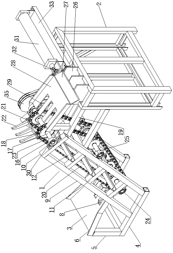
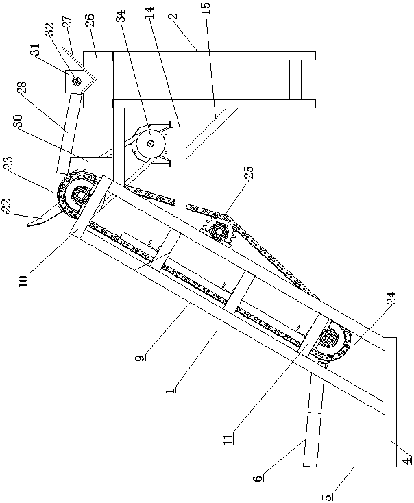
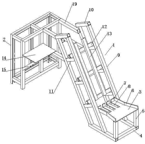
[0021] Such as Figure 1-3 As shown, a chain feeding device includes a feeding rack 1, and the feeding rack 1 includes two groups of rack bodies, left and right, and each group of rack bodies includes two inclined brackets 9 respectively, and the included angle between the inclined brackets 9 and the horizontal plane is 60°, the upper ends of the two inclined brackets 9 are connected with a first connecting rod 10, and the included angle between the first connecting rod 10 and the horizontal plane is 30°. Some reinforcing connecting rods 11 are connected between the two inclined brackets 9 below the first connecting rod 10, and some reinforcing connecting rods 11 are all parallel to the first connecting rod 10, and the lower end of the feeding frame 1 is connected with the base frame 4, and the base frame 4. It is arranged horizontally. There are some reinforced cross bars 12 connected between the left and right two groups of frames. Several reinforced cross bars 12 are arrang...


PUM


Abstract

The invention relates to a chain feeding device. The chain feeding device comprises a feeding support. The feeding support comprises a left support body group and a right support body group. Each support body group comprises two oblique support bodies. Three chain wheel components are arranged on the feeding support and include the first chain wheel assembly, the second chain wheel assembly and the tensioning chain wheel assembly. The chain feeding device is simple in overall structure, small in transmission stage number, uniform in conveying, low in economic cost, easy to implement and convenient to use and popularize widely. By means of the device, multiple materials are placed into a feeding hopper in sequence, the chain feeding device automatically conveys the materials to a discharging outlet, the materials automatically roll to a next station, and manpower is saved; and as long as the materials are fed on time, uniform feeding can be kept under the condition that the motor set speed is fixed, and the working urgency sense of master workers is relieved.

Description

technical field [0001] The invention relates to a material conveying device, in particular to a chain feeding device. Background technique [0002] In recent years, the domestic industry has made great development and progress, and put forward higher requirements for product materials, quality and environmental protection, and more and more manufacturers have eliminated old processes and used intermediate frequency furnaces. The heat treatment environment is harsh, and material loading is the first link, and the physical strength is heavy. Many manufacturers still do it manually during heat treatment. In order to reduce the labor intensity of workers or better adapt to the productivity of factory workpieces, it is necessary to equip the induction heating furnace with an automatic feeding device when the number of heavy and long single workpieces is large. However, in the current heat treatment automation equipment market, the structure of the feeding device is complicated, ...

Claims


Application Information

Patent Timeline
Patent Type & Authority Applications(China)
IPC IPC(8): B65G23/06B65G23/44B65G23/22B65G23/30B65G17/12B65G47/82
CPCB65G23/06B65G17/12B65G23/22B65G23/30B65G23/44B65G47/82
Inventor 张三强王永华薛延杰刁立龙赵宏帅崔维相
Owner 潍坊信合节能科技有限公司
Why Eureka
Try Eureka