Water quantity recording meter

A technology for recording meters and water volume, applied in the field of machinery, can solve problems such as inconvenient control of water volume and affecting configuration efficiency

Pending Publication Date: 2019-03-19
南京市江宁医院
View PDF0 Cites 2 Cited by
  • Summary
  • Abstract
  • Description
  • Claims
  • Application Information

AI Technical Summary

Problems solved by technology

[0003] The purpose of the present invention is to provide a water volume recording table to solve the problem that the water volume is inconvenient to control and affect the allocation efficiency when disposing the disinfectant proposed in the above background technology

Method used


Image

  • Water quantity recording meter
  • Water quantity recording meter
  • Water quantity recording meter

Examples


Embodiment 1

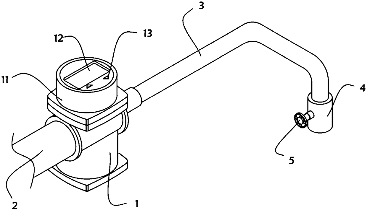
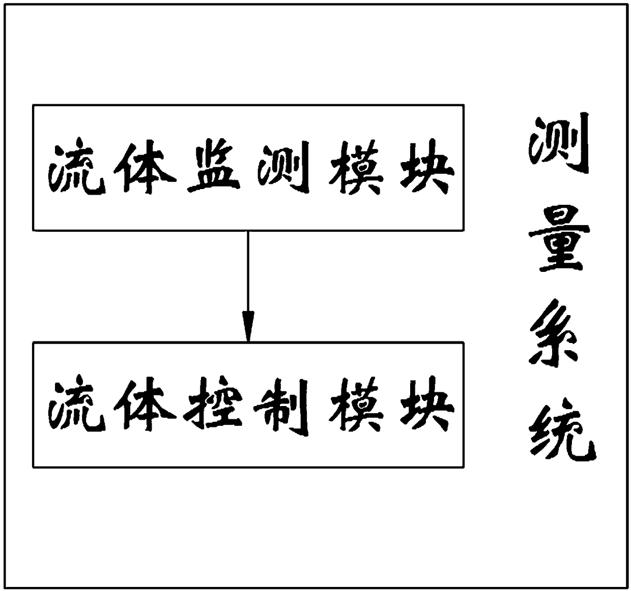
[0064] water volume records, such as figure 1 and figure 2 As shown, it includes a volumetric flowmeter 1, one end of the volumetric flowmeter 1 is provided with a water inlet pipe 2, the other end of the volumetric flowmeter 1 is provided with a drainage pipe 3, and the other end of the drainage pipe 3 is installed with a faucet 4, and the faucet 4 An ordinary valve 5 for controlling the water output of the faucet 4 is installed on the outer wall. A measuring system 11 is installed on the top of the positive displacement flowmeter 1. A display screen 12 and buttons 13 are respectively installed on the top of the measuring system 11. The inside of the measuring system 11 includes a fluid monitoring module. and a fluid control module, the fluid monitoring module is used to detect and digitally display the fluid flow passing through the positive displacement flowmeter 1 , and the fluid control module is used to control the fluid flow passing through the positive displacement fl...

Embodiment 2

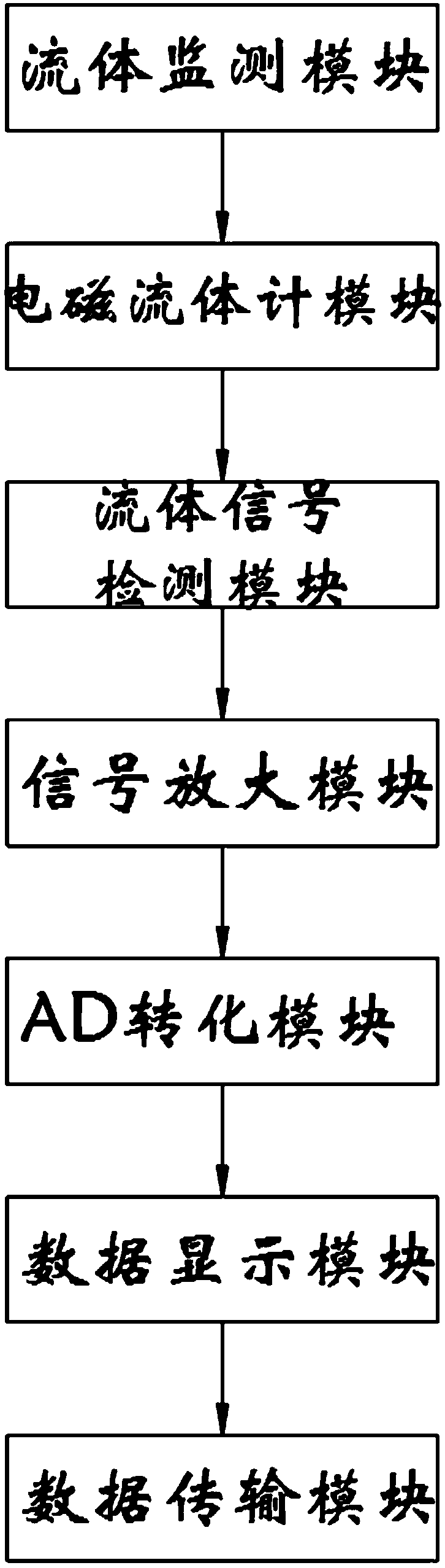
[0071] As a second embodiment of the present invention, in order to facilitate the detection of fluid flow, the inventors set up a fluid detection module, as a preferred embodiment, such as image 3 As shown, the fluid monitoring module includes an electromagnetic fluid meter module, a fluid signal detection module, a signal amplification module, an AD conversion module, a data display module and a data transmission module. The electromagnetic fluid meter module is used as a flow sensor and collects fluid flow information. The fluid signal detection module is used to detect the information of the fluid flow, the signal amplification module is used to amplify the detected fluid flow information, and the AD conversion module is used to convert the continuous analog quantity into a discrete digital quantity acceptable to the microcontroller, and the data The display module is used to digitally display the detected fluid flow on the display screen 12, and the data transmission modu...

Embodiment 3

[0080] As a preferred embodiment, in order to facilitate the detection of fluid signals, the inventors set up a fluid signal detection module, as a preferred embodiment, such as Figure 7 As shown, the fluid signal detection module includes an electromagnetic induction module, an induced electromotive force module and a volume flow detection module. The electromagnetic induction module detects the electromagnetic intensity generated when the fluid passes by according to Faraday's law of electromagnetic induction, and the induced electromotive force module is used to detect the induced electromotive force in the electrode. The volume flow detection module detects the volume flow of the fluid.

[0081] In this embodiment, the electromagnetic induction module is based on Faraday’s law of electromagnetic induction. When the conductor moves in the magnetic field and cuts the magnetic force line, an induced electromotive force e will be generated at its two ends. Its direction is det...


PUM


Abstract

The invention relates to the technical field of machinery, in particular to a water quantity recording meter comprising a volumetric flow meter. The top of the volumetric flow meter is equipped with ameasuring system. The measuring system internally comprises a fluid monitoring module and a fluid control module. The water quantity recording meter is provided with the fluid monitoring module, an electromagnetic fluid meter module is used as a flow sensor to collect fluid flow information, the continuous analog quantity is converted into the discrete digital quantity acceptable to a single chipcomputer through an AD conversion module, and finally a data display module is adopted to display the detected fluid flow on a display screen digitally to achieve real-time monitoring of the fluid flow. Through the set fluid control module, control system data is formed by linear combination of proportional, integral and differential of the deviation by a PID system module, and a valve module iscontrolled through a motor module. At the same time, the fluid flow is set through a keyboard inputting module and displayed digitally on the display screen to achieve control of the fluid flow.

Description

technical field [0001] The invention relates to the technical field of machinery, in particular to a water volume recording table. Background technique [0002] In clinical use, chlorine-containing disinfectants are often prepared. For example, to configure 500mg / L chlorine-containing disinfectants, one 500mg disinfection tablet and 1000ml of tap water need to be put in. When tap water is put in, a measuring cup is usually required to measure or Draw the scale line on the bucket, but the scale line on the bucket is easy to fall off after a long time, and using a measuring cup is too troublesome when a large amount of tap water is needed, which affects the efficiency of configuration. In view of this, we propose a water volume recording table. Contents of the invention [0003] The purpose of the present invention is to provide a water volume recording table to solve the problem that the water volume is inconvenient to control when distributing the disinfectant proposed in...

Claims


Application Information

Patent Timeline
Patent Type & Authority Applications(China)
IPC IPC(8): G01F1/58G01F1/60G01F11/00G01F15/06G05D7/06
CPCG01F1/58G01F1/60G01F11/00G01F15/06G05D7/0617G05D7/0635
Inventor 陈超
Owner 南京市江宁医院
Why Eureka
Try Eureka