Wall-attached stabilizing device for hydraulic engineering concrete tester

A water conservancy engineering and concrete technology, which is applied to measuring devices, instruments, scientific instruments, etc., can solve problems such as failure to filter concrete dust normally, surface damage of fair-faced concrete walls, and easy breakage of strike rods.

Inactive Publication Date: 2019-03-19
王世洛
View PDF0 Cites 1 Cited by
  • Summary
  • Abstract
  • Description
  • Claims
  • Application Information

AI Technical Summary

Problems solved by technology

[0003] 1. When the concrete rebound tester detects concrete, it is necessary to artificially hold the bullet dry against the surface of the concrete. The concrete rebound tester has a relatively long bullet dry bar, because the hand-held personnel cannot hold the concrete rebound tester when squeezing the elastic rod. The bullet dry is in the horizontal position, causing the concrete hammer to be in a tilted state when it is squeezed and contracted, and the tilted contraction of the bullet dry can easily squeeze the dust-proof sealing ring inside the cap to make the dust-proof seal One side of the ring is continuously stressed and skewed, which cannot filter the external concrete dust normally
[0004] 2. At the same time, when using the concrete rebound tester to test the strength of clear-water concrete, put the bullet dry in contact with the surface of the clear-water concrete to apply pressure. Since the surface of the clear-water concrete is smooth and smooth, when the surface of the clear-water concrete is squeezed with the bullet dry, the bullet dry is flat and smooth. The uneven force on the surface of the fair-faced concrete makes the bullet dry slide out along the fair-faced concrete, and the bullet dry is easy to break, and it will also cause damage to the surface of the fair-faced concrete wall

Method used


Image

  • Wall-attached stabilizing device for hydraulic engineering concrete tester
  • Wall-attached stabilizing device for hydraulic engineering concrete tester
  • Wall-attached stabilizing device for hydraulic engineering concrete tester

Examples


Embodiment

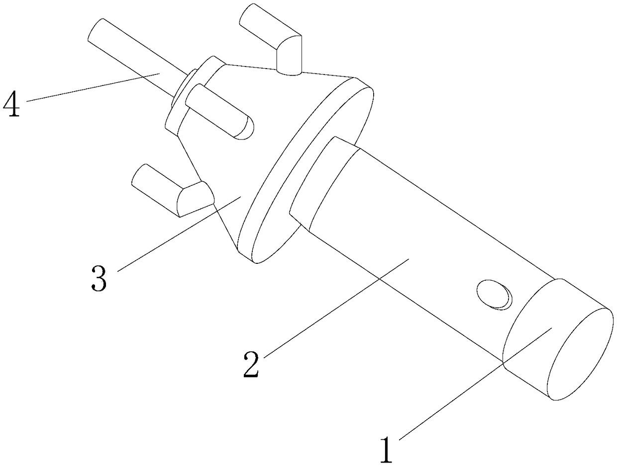
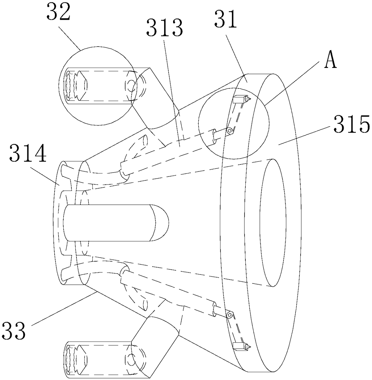
[0023] Such as Figure 1-Figure 6 As shown, the present invention provides a wall-mounted stabilizing device for a hydraulic engineering concrete detector, the structure of which includes a rear bracket 1, a body 2, a wall-mounted stabilizing device 3, and an ejection rod 4. The rear bracket 1 is wound around the body 2, the body 2 runs through the interior of the wall-attaching stabilization device 3, and the ejection rod 4 is embedded in the interior of the body 2, and the wall-attaching stabilization device 3 includes an expanding lock mechanism 31 and a flat suction mechanism 32 1. Outer shell 33, said lock expansion mechanism 31 and horizontal suction mechanism 32 mechanically cooperate through pipelines, said lock expansion mechanism 31 is horizontally installed inside the shell 33, and said flat suction mechanism 32 is installed on the outside of shell 33 through the outer pipe cover side.

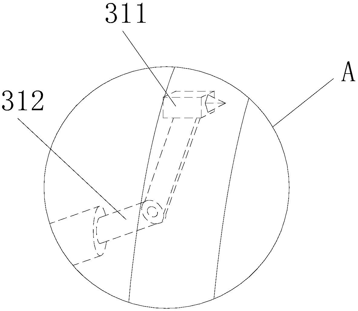
[0024] The lock expansion mechanism 31 includes a conical foot rail 311, an ar...


PUM


Abstract

The invention discloses a wall-attached stabilizing device for a hydraulic engineering concrete tester. The wall-attached stabilizing device structurally comprises a rear carrier sleeve, a body, a wall-attached stabilizing unit, and an elastic impact rod. An outer rotating ring is rotated to drive conical base rails to rotationally contract; arc connection rods are moved leftward so that inner pressure of communicating pipes varies to push pushing connection discs; the pushing connection discs push pasting discs to drive tough needles to extend out; the multiple tough needles on a combinationdisc extend out at the same time to slightly lock the surface of a concrete wall; the combination of the tough needles is in ring shape, so that area of contact with the surface of concrete is enlarged; the elastic impact rod never skews when a concrete resiliometer performs detecting; it is ensured that the elastic impact rod never crushes a seal ring to cause deformation; the seal ring allows normal filtering of concrete dust; normal discs help temporarily prevent slip on dry concrete walls; the elastic impart rod never slips when detecting dry concrete; the elastic impact rod never damages;the surface of the dry concrete wall is never damaged.

Description

technical field [0001] The invention relates to the field of water conservancy engineering, in particular to a wall-attaching and stabilizing device for a hydraulic engineering concrete detector. Background technique [0002] For the quality inspection of concrete in hydraulic engineering, the concrete rebound instrument bounces the concrete surface with the bullet hammer through the bullet hammer, and receives the restoring force of the reverse instantaneous elastic deformation, and detects the concrete by the distance of the restoring force rebounding the hammer Compressive strength, but when the existing concrete rebound meter detects fair-faced concrete (the surface is smooth and smooth, the color is uniform, the edges and corners are sharp, and there is no bump damage and pollution), there are the following problems: [0003] 1. When the concrete rebound tester detects concrete, it is necessary to artificially hold the bullet dry against the surface of the concrete. The...

Claims


Application Information

Patent Timeline
IPC IPC(8): G01N3/02G01N3/52
CPCG01N3/02G01N3/52G01N2203/0083
Inventor 王世洛
Owner 王世洛
Why Eureka
Try Eureka