
Flight detecting device, imaging system and radiation detecting method thereof

A technology of a detection device and an imaging system, applied in the field of radiation detection, can solve the problems of UAV signal interference, certain requirements for shooting distance, and inability to detect, so as to improve detection capabilities and detection safety, and detect target objects at long distances. , the effect of improving the detection speed

Inactive Publication Date: 2019-03-19
RAYCAN TECH CO LTD SU ZHOU
View PDF14 Cites 1 Cited by
  • Summary
  • Abstract
  • Description
  • Claims
  • Application Information

AI Technical Summary

Problems solved by technology

However, because UAVs are easily disturbed by signal interference and human factors, and have certain requirements for shooting distance, they cannot complete the detection well, and because ordinary light shooting is based on the appearance information seen, it is difficult to Easily misled by false signals from target audience
Moreover, at present, for some target objects that are not on the surface, such as nuclear submarines, it is not possible to use the technology taken by drones to determine their specific positions

Method used


Image

  • Flight detecting device, imaging system and radiation detecting method thereof
  • Flight detecting device, imaging system and radiation detecting method thereof
  • Flight detecting device, imaging system and radiation detecting method thereof

Examples


Embodiment Construction

[0049] The technical solutions in this application will be clearly and completely described below in conjunction with the accompanying drawings in this application. Apparently, the described embodiments are only used to explain some of the embodiments of this application, not all of them. It is not intended to limit the scope of the application or the claims. Based on the embodiments in this application, all other embodiments obtained by persons of ordinary skill in the art without making creative efforts shall fall within the scope of protection of this application.

[0050]It should be noted that when an element is referred to as being “disposed on” another element, it may be directly disposed on the other element or there may also be an intervening element. When an element is referred to as being "connected / coupled" to another element, it can be directly connected / coupled to the other element or intervening elements may also be present. As used herein, the term "connected / ...


PUM


Abstract

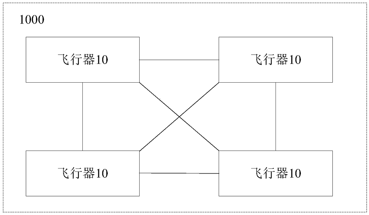
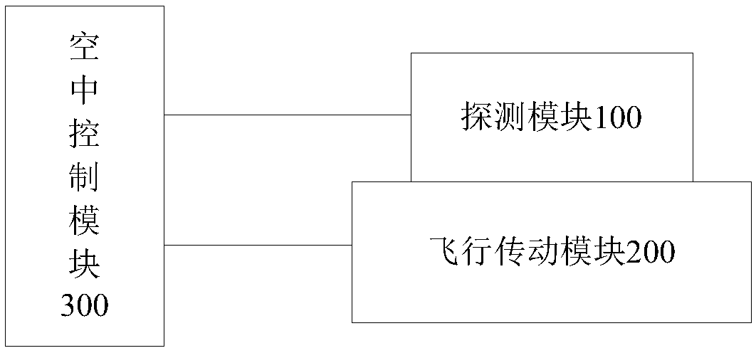
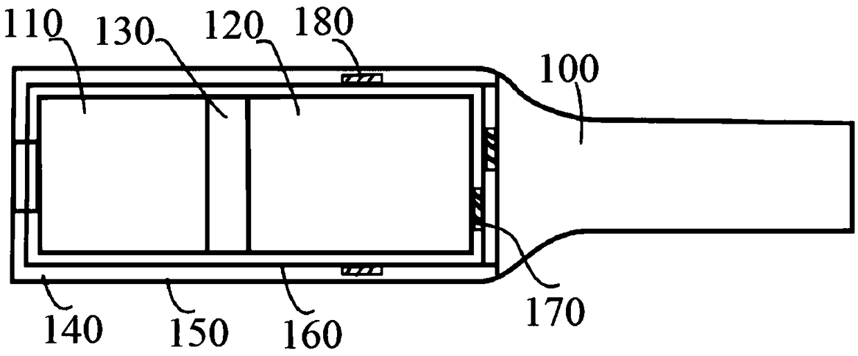
The invention discloses a flight detecting device, an imaging system and a radiation detecting method thereof. The flight detecting device comprises a plurality of communicated aircrafts. Each aircraft comprises a detecting module, a flight transmission module and an overhead control module, wherein the detecting module is configured to perform detection according to an obtained detection indication instruction, and comprises a scintillating crystal for receiving radioactive rays transmitted by a target object and generating corresponding optical signals and a photoelectric converter for converting the optical signals into electric signals; the flight transmission module is configured to bear the detecting module and perform flying according to an obtained flight indication instruction; the overhead control module is configured to control operation of the detecting module and the flight transmission module according to an obtained task instruction and send detecting data to a ground monitoring device according to feedback information sent by the detecting module and / or the flight transmission module so as to determine the position of the target object. By means of the technical scheme, the purpose of remotely detecting the target object can be achieved.

Description

technical field [0001] The present application relates to the technical field of radiation detection, in particular to a flight detection device, an imaging system and a radiation detection method thereof. Background technique [0002] The descriptions in this section merely provide background information related to the disclosure in this application and may not constitute prior art. [0003] In the prior art, in order to determine the specific location of the target object, it can be detected by using a UAV to take pictures. However, because UAVs are easily disturbed by signal interference and human factors, and have certain requirements for shooting distance, they cannot complete the detection well, and because ordinary light shooting is based on the appearance information seen, it is difficult to Easily misled by false signals from the target audience. Moreover, at present, for some target objects that are not on the surface, such as nuclear submarines, it is not possib...

Claims


Application Information

Patent Timeline
Patent Type & Authority Applications(China)
IPC IPC(8): G01T1/202
CPCG01T1/202
Inventor 邓贞宙欧阳微王玉皞牛广达
Owner RAYCAN TECH CO LTD SU ZHOU
Learn More