Current transformer assembly device

A technology for assembling devices and current collectors, which is applied in the manufacture of inductors/transformers/magnets, electrical components, circuits, etc., which can solve the problems of low efficiency of current collectors and achieve high efficiency.

Pending Publication Date: 2019-03-19
青岛美磁新能源电子有限公司
View PDF7 Cites 0 Cited by
  • Summary
  • Abstract
  • Description
  • Claims
  • Application Information

AI Technical Summary

Problems solved by technology

[0002] The invention patent (Patent No. 201820261673.6) discloses a current comparator, including a magnetic core, windings and a base. At the same time, glue needs to be dispensed in the base, and then the magnetic core is placed in the base, and then the magnetic core is stamped to be pressed tightly in the base. The processing of current comparators in the prior art has the problem of low efficiency.

Method used


Image

  • Current transformer assembly device
  • Current transformer assembly device

Examples


Embodiment 1

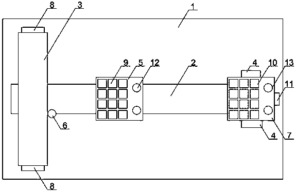
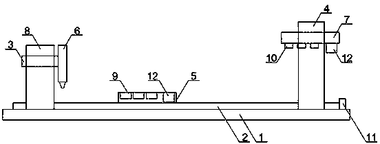
[0018] like Figure 1~2 As shown, a current comparator assembly device includes table 1, x-guiding rail 2, y-guiding rail 3, z-guiding rail 4, lower mold 5, dispensing gun 6 and upper mold 7, x-guiding rail 2, y-guiding The guide rail 3 and the z guide rail 4 are set on the table top 1, the y guide rail 3 is set above one end of the x guide rail 2 through the bracket 8, the z guide rail 4 is set on the other end of the x guide rail 2, and the lower mold 5 is set on the x On the guide rail 2, the upper surface of the lower mold 5 is provided with a number of placement grooves 9 in the form of a matrix, the dispensing gun 6 is set on the y guide rail 3, and the lower mold 5 walks on the x guide rail 2 to the y direction When the guide rail 3 is below, the dispensing gun 6 walks on the y guide rail 3, and its gun head points to each placement groove 9 of the lower mold 5y upwards. The upper mold 7 is arranged on the z guide rail 4, and the lower surface of the upper mold 7 is pro...


PUM


Abstract

The invention discloses a current transformer assembly device, which comprises an x-direction guiding rail, a y-direction guiding rail, a z-direction guiding rail, a lower mold, a glue dispensing gunand an upper mold, wherein the lower mold is arranged on the x-direction guiding rail; the glue dispensing gun is arranged on the y-direction guiding rail, and the upper mold is arranged on the z-direction guiding rail. The current transformer assembly device is used for assembling and forming a magnetic core and a base seat in the current transformer, and has the advantage of high efficiency.

Description

technical field [0001] The invention relates to the technical field of electronic device processing equipment, in particular to a current comparator assembly device. Background technique [0002] The invention patent (Patent No. 201820261673.6) discloses a current comparator, including a magnetic core, windings and a base. The winding is wound on the base, and a space corresponding to the magnetic core passes is set on the base. At the same time, glue needs to be dispensed in the base, and then the magnetic core is placed in the base, and then the magnetic core is stamped to be pressed tightly in the base. The processing of the current comparator in the prior art has the problem of low efficiency. [0003] In view of this, propose this invention especially. Contents of the invention [0004] In view of the deficiencies in the prior art, the purpose of the present invention is to provide a current comparator assembly device for assembling the magnetic core and the base in ...

Claims


Application Information

Patent Timeline
Patent Type & Authority Applications(China)
IPC IPC(8): H01F41/00
CPCH01F41/00
Inventor 吕红专江松
Owner 青岛美磁新能源电子有限公司
Why Eureka
Try Eureka