
Intelligent battery system

An intelligent battery and battery technology, applied in secondary batteries, battery circuit devices, arrangement of multiple synchronous batteries, etc., can solve the problems of wasting resources, exceeding the cost, and being unable to replace, and achieve low cost, extended life, and battery utilization. high rate effect

Pending Publication Date: 2019-03-19
深圳奥丹新能源应用技术有限公司
View PDF0 Cites 1 Cited by
  • Summary
  • Abstract
  • Description
  • Claims
  • Application Information

AI Technical Summary

Problems solved by technology

However, the existing technology has three defects. The first defect is that when the battery is split from the group state into a separate and disconnected state, the data of each battery cannot be obtained locally in the battery; the second is that it is necessary to know in advance that the group The number of battery strings, and then customize a set of circuits according to this number of strings to adapt to this battery pack, that is to say, the batteries cannot be self-adapted into groups; the third defect is that adding related battery management equipment (circuits) needs to be customized. There are many lines and cannot be standardized
The above three defects make the application of batteries still require professionals and institutions to operate and pay higher costs, and it is impossible to realize the function of smart batteries
For example, the battery of an electric car, referring to a fuel car, is the gasoline in the fuel tank. It should be standard and easy to obtain, but it is currently not possible. Whichever brand of electric car you choose, you must use its supporting battery pack, which cannot be replaced; If you use smart batteries, as long as they are of the same model, they can be easily exchanged
Besides, the decommissioned batteries of electric vehicles (SOH is about 70%, that is, the power after fully charging is 70% of the nominal value), currently cannot be used in stages, because the cost of regrouping exceeds that of using new batteries, they can only be scrapped and recycled. wasted resources

Method used


Image

  • Intelligent battery system
  • Intelligent battery system

Examples


Embodiment Construction

[0037] The present invention provides an intelligent battery system. In order to make the purpose, technical solutions and effects of the present invention clearer and clearer, the present invention will be further described in detail below with reference to the accompanying drawings and examples. It should be understood that the specific embodiments described herein are only used to explain the present invention, but not to limit the present invention.

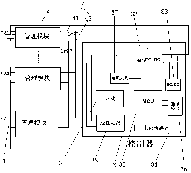
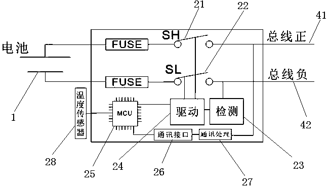
[0038] see figure 1 , an intelligent battery system provided by the present invention includes at least one battery module 1, a management module 2 having the same quantity as the battery module 1 and installed on the battery module 1, at least one controller 3 and a positive and negative connection bus 4 , the positive and negative connection bus 4 includes a positive connection bus 41 and a negative connection bus 42, wherein the positive and negative electrodes of the battery series group formed by the battery modules 1 co...


PUM


Abstract

The invention discloses an intelligent battery system, and the system comprises at least one battery module, management modules which are mounted on the battery modules and are equal in number to thebattery modules, at least one controller and a positive and negative connection bus, wherein the positive and negative electrodes of a battery series group formed by the series connection of the battery modules are connected with the controller, and the positive and the negative electrodes of each battery module are connected with the management modules connected with the battery modules, and eachmanagement module and the controller are also connected in parallel through the positive and negative connection bus. The system realizes data and energy transmission by utilizing two connection buses, and realizes transferring of energy of a high-energy battery to a low-energy battery, thereby achieving active balancing, prolonging battery life and working time of each operation. Moreover, the cost is lower.

Description

technical field [0001] The invention relates to the field of new energy battery management, in particular to an intelligent battery system. Background technique [0002] Batteries have been widely used since their invention, especially power batteries represented by lithium batteries have become more and more widely used, from industrial energy storage, electric vehicles and even household energy storage. Although it has been widely used, the evaluation of the state of a single battery and the use of a series in a group has always been a more professional (difficult, high cost) thing. For example, the remaining power (SOC) of the battery can only be known after constant current discharge with a professional discharge meter, but it is no longer meaningful for the application at this time, because the power has been discharged; another example is the degree of health (SOH) of the battery. , it is even more difficult to have a device that can measure it directly. How to easil...

Claims


Application Information

Patent Timeline
IPC IPC(8): H02J7/00H01M10/48
CPCH01M10/482H01M10/486H02J7/0014H02J7/0048H02J7/342H01M10/4257Y02E60/10
Inventor 宋天来
Owner 深圳奥丹新能源应用技术有限公司
Learn More