Liquid container for warming infusion or flushing and application method thereof

A liquid container and infusion technology, applied in the fields of blood transfusion, clinical flushing, and medical infusion, can solve the problems of slow heat conduction, inconvenience, long pipeline, etc., to save working pressure, improve work efficiency, and reduce the probability of reverse insertion.

Pending Publication Date: 2019-03-22
天津沃姆斯医疗器械有限公司
View PDF12 Cites 0 Cited by
  • Summary
  • Abstract
  • Description
  • Claims
  • Application Information

AI Technical Summary

Problems solved by technology

[0004] The infusion tube of patent No. ZL 200420036761.4 is mainly heated by placing the pipeline into a heating device. This method has a very limited heating area of ​​the pipeline, and often the liquid in the pipeline has not been heated to a temperature and has already flowed downstream. Therefore, on this issue, some The method is to put the bag directly into the heating device, or set a very high temperature on the heating device to achieve the purpose of rapid heating, such as the patent number: ZL 03241419.6, but it also causes plastic packaging or pipelines to be exposed to high temperature. Safety hazards of melting or precipitation of chemical substances
There are also solutions that coil the pipeline inside the heating device to increase the heating area, such as patent number: ZL 201520889903.X, patent number: ZL 201730673014.4, and patent application number: ZL201830317017.9. The heating area also makes the pipeline quite long. Too long pipeline is very easy to kink or hang on other items during use, and it is very inconvenient to coil the pipeline every time it is used, and the above Both solutions have slow heat conduction due to the specific thickness of the infusion line itself, and the use effect is not good

Method used


Image

  • Liquid container for warming infusion or flushing and application method thereof
  • Liquid container for warming infusion or flushing and application method thereof
  • Liquid container for warming infusion or flushing and application method thereof

Examples


Embodiment Construction

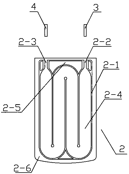
[0019] Such as figure 1 As shown, the liquid container for warming infusion or flushing includes a frame 1 , a bag body 2 , a liquid inlet tube 3 , and a liquid outlet tube 4 .

[0020] Such as Figure 4 As shown, several welding wires 2-1 are thermally welded on the bag body 2, and several welding wires 2-1 and the bag body 2 form a liquid inlet 2-2, a liquid outlet 2-3, a bag body junction 2-5 and A serpentine curved flow channel 2-4, the liquid inlet 2-2 and the liquid outlet 2-3 are respectively located at the two ends of the serpentine curved flow channel 2-4, and the bag body connection 2-5 is arranged between the liquid inlet 2-2 and the liquid outlet 2-3. Several welding lines 2-1 between the liquid outlets 2-3 are peripherally connected to the bag body 2-6;

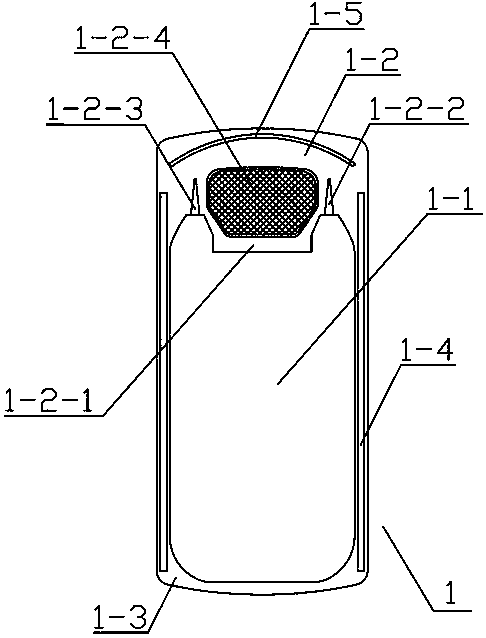
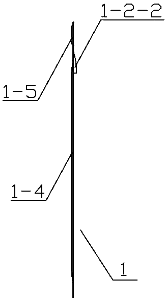
[0021] Such as Figure 2-3 As shown, the middle part of the frame 1 is a hollow part 1-1, the upper part is a hand-held part 1-2, the outer edge frame connecting side 1-3, and the frame connecting side 1-3 on ...


PUM


Abstract

The invention relates to a liquid container for warming infusion or flushing and an application method thereof. The liquid container comprises a framework, a bag body, a liquid inlet pipe and a liquidoutlet pipe, wherein a bag body connecting edge of the bag body is welded on a framework connecting edge of the framework, a bag body joint of the bag body is welded on a framework joint, when in use, a handhold part of the framework is held by a hand of an operator, whether an insertion direction of the liquid container is correct is determined by confirming whether a tag position faces upwardly, then the liquid container is slowly inserted into a warming apparatus until the liquid container cannot be pushed, other pipelines are connected according to the infusion or flushing operation requirements, the liquid container is fully filled with liquid, and finally the warming apparatus is started, so that the infusion or flushing operation can be carried out. By virtue of a built-in curve runner design of the novel liquid bag, on the basis of not changing a basic length of the original infusion apparatus, the heated area is increased, and the liquid is safely and rapidly warmed to a comfortable temperature.

Description

technical field [0001] The invention relates to a liquid container for warming infusion or flushing and its use method, which is used in conjunction with an infusion set, a blood transfusion set or a flushing apparatus, and is especially used in medical infusion, blood transfusion and clinical flushing. Background technique [0002] Warming fluid infusion is an important clinical fluid replacement method, especially for infusion of large volumes of cryogenic fluids or rapid infusion of large volumes of refrigerated blood. Due to the low temperature of the infused liquid, a large amount of infusion will lead to hypothermia, which will bring great harm to the patient, such as surgical incision infection, cardiovascular adverse events, decreased blood coagulation function, prolonged recovery time from anesthesia, and prolonged hospital stay. The liquid needs to be warmed. [0003] At present, the commonly used clinical heating methods include water bath heating, incubator heat...

Claims


Application Information

Patent Timeline
Patent Type & Authority Applications(China)
IPC IPC(8): A61M5/44A61M3/02G05D23/22
CPCA61M3/02A61M5/445G05D23/22A61M2205/3368A61M2205/18A61M2205/3653A61M2205/127
Inventor 刘继航
Owner 天津沃姆斯医疗器械有限公司
Why Eureka
Try Eureka