
Riveting device and method for locking bearing case assembly and liner assembly

A technology for riveting devices and components, applied in assembly machines, metal processing, metal processing equipment, etc., can solve the problems of uneven force, low production efficiency, high production cost, etc., to avoid radial offset, uniform force, The effect of increasing rigidity

Active Publication Date: 2019-03-22
SHENYANG LIMING AERO-ENGINE GROUP CORPORATION
View PDF5 Cites 6 Cited by
  • Summary
  • Abstract
  • Description
  • Claims
  • Application Information

AI Technical Summary

Problems solved by technology

[0003] In the existing riveting device and method used after the combined assembly of the supporting casing assembly and the bushing assembly, the automatic centering of the supporting casing, the bushing, and the spacer bushing cannot be realized, and the single-point riveting is used to apply the load, resulting in insufficient force on each component. uniform, resulting in the radial offset of each component during the riveting process, the riveting design requirements of the assembly cannot be guaranteed, and the single-point riveting is repeatedly disassembled and measured, resulting in low assembly quality, long assembly cycle, low production efficiency, and production costs. high

Method used


Image

  • Riveting device and method for locking bearing case assembly and liner assembly
  • Riveting device and method for locking bearing case assembly and liner assembly
  • Riveting device and method for locking bearing case assembly and liner assembly

Examples


Embodiment Construction

[0031] The present invention will be further described below in conjunction with the accompanying drawings and specific embodiments.

[0032] The purpose of the present invention is to provide a riveting device and method for locking and supporting the casing assembly and the bushing assembly, which can realize the automatic centering of the supporting casing, the bushing and the spacer bushing, and can realize the simultaneous application of loads on the points so that the Each component is evenly stressed, avoiding radial deviation of each component during the riveting process, ensuring the riveting design requirements of the assembly, improving assembly quality, shortening assembly cycle, thereby improving production efficiency and reducing production costs.

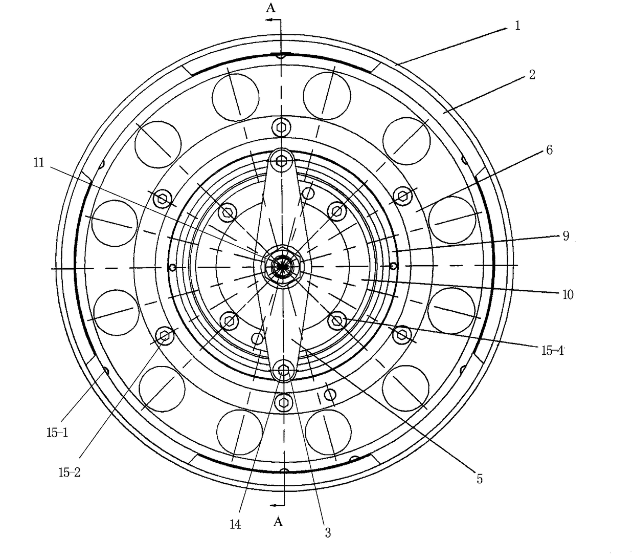
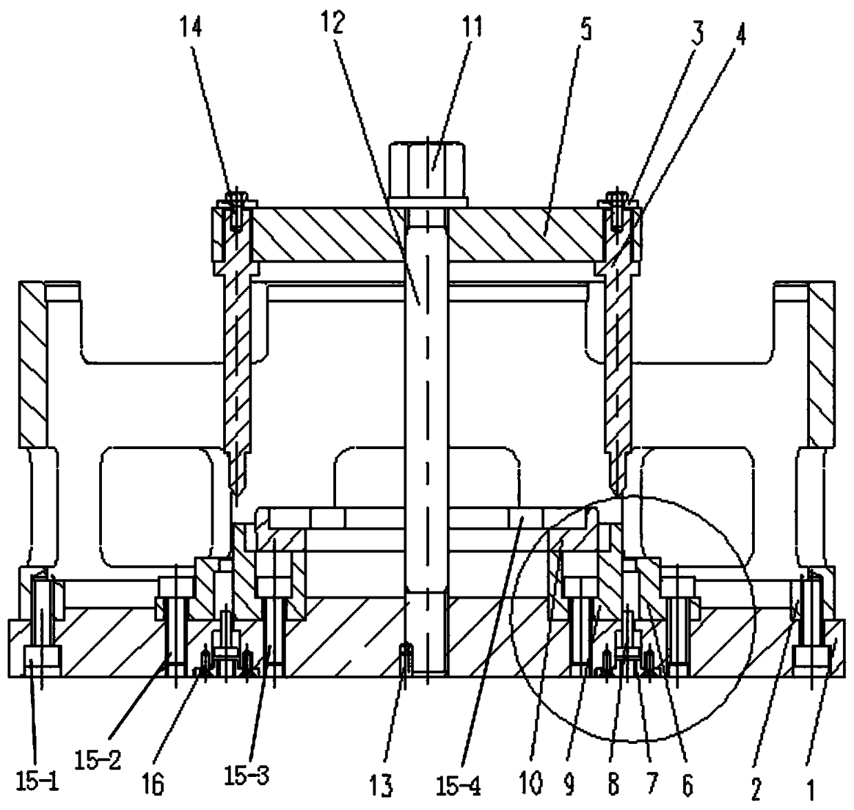
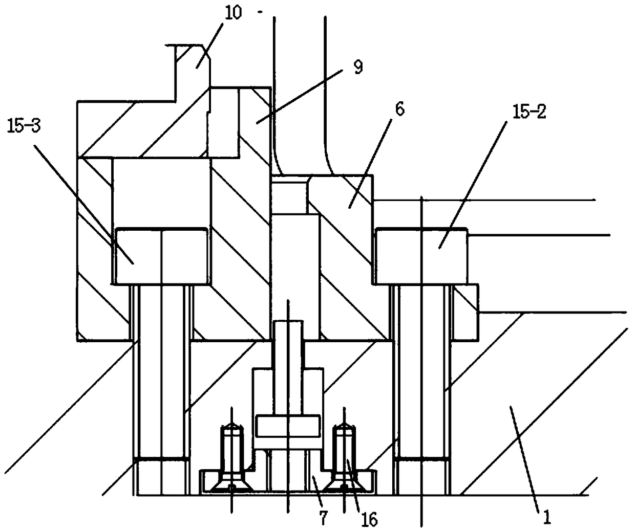
[0033] Such as figure 1 and figure 2As shown, they are the top view and the A-A sectional view of the riveting device for locking and supporting the casing assembly and the bushing assembly of the present invention,...


PUM


Abstract

The invention relates to the technical field of aero-engine assembly and manufacturing, and provides a riveting device and method for locking a bearing case assembly and a liner assembly. The device comprises a large positioning ring, a medium positioning ring and a small positioning ring which are matched with a bearing case spigot, the outer side wall of a spacer liner and the inner side wall ofa liner separately, a tray for jacking the heads of rivets, an ejector rod for jacking the lower end face of the spacer liner, a pressing plate which is vertically adjustable and rotatable, and centers. In the method, firstly, the three positioning rings are utilized for achieving automatic centering of the assemblies; the pressing plate is utilized for driving the two radially symmetric centersfor extruding the two symmetrical rivets till deformation is qualified; and then the pressing plate is rotated for pressing the next set of rivets. With the riveting device and method, automatic centering of a bearing case, the liner and the spacer liner can be achieved, and simultaneous counter-point load application can be achieved, so that the assemblies are stressed uniformly and are free of radial deviation in the riveting process, and the riveting design requirement of the combination is ensured.

Description

technical field [0001] The invention relates to the technical field of aero-engine assembly and manufacturing, in particular to a riveting device and method for locking and supporting a casing assembly and a bushing assembly. Background technique [0002] After the traditional aero-engine supporting casing assembly and the bushing assembly are combined and riveted, combined processing is not required. With the development of aero-engines, new design structures are also produced. The bushing assembly is assembled to the supporting casing assembly for riveting and combined processing is required. Therefore, new requirements are put forward for the existing assembly and manufacturing technology. [0003] In the existing riveting device and method used after the combined assembly of the supporting casing assembly and the bushing assembly, the automatic centering of the supporting casing, the bushing, and the spacer bushing cannot be realized, and the single-point riveting is use...

Claims


Application Information

Patent Timeline
IPC IPC(8): B23P21/00B23P19/00
CPCB23P19/00B23P21/00
Inventor 王娜刘丛辉林东巩孟祥杜宝玉
Owner SHENYANG LIMING AERO-ENGINE GROUP CORPORATION
Learn More