

Method and system for localizing charging interface
A positioning method and positioning system technology, which are applied in charging stations, electric vehicle charging technology, electric vehicles, etc., can solve the problems of unstable positioning accuracy, low positioning efficiency, and high cost of visual positioning systems, and achieve simple positioning methods and high efficiency. Effect
- Summary
- Abstract
- Description
- Claims
- Application Information
AI Technical Summary
Problems solved by technology
Method used
Image

Examples
Embodiment 1
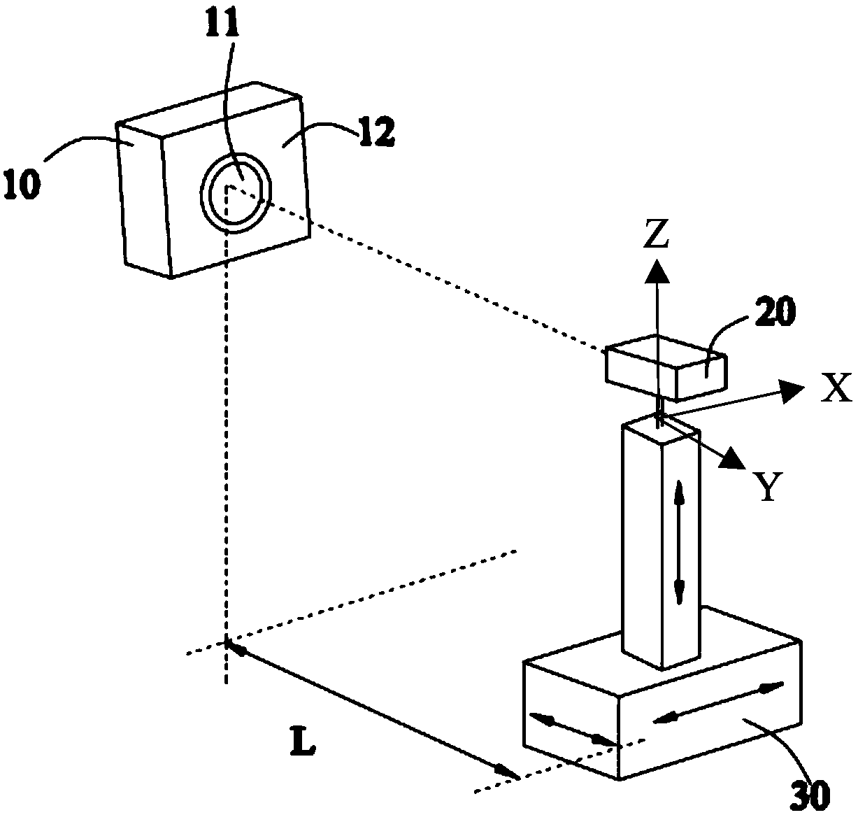
[0053] ginseng figure 1 As shown, the positioning system in this embodiment is composed of a charging base 10, a laser ranging module 20, and a mechanical arm 30. The charging base 10 includes a base 12 and a circular charging port 11 located on the base. The shape of 11 is a tube with a certain wall thickness, and there is a certain height difference between its end surface and the end surface of the base 12, and the end surface of the base 12 is a plane.
[0054] The robotic arm 20 can drive the laser ranging module 20 to move along the X-axis, Y-axis and Z-axis, so the positioning system can adjust the distance L between the laser ranging module 20 and the charging port 11 in the Y direction through the mechanical arm 20, preferably in this implementation The distance L in the example is 0.2m to 0.6m, which can ensure the measurement accuracy. In addition, the positioning system can also adjust the position of the laser spot emitted by the laser ranging module 20 relative ...
Embodiment 2
[0072] Different from Embodiment 1, the base and the charging port of the charging stand in this embodiment are integrated, and the shape of the charging port is a conical surface.
[0073] The advantage of this embodiment is that the characteristics of the charging port are obvious, even if there is light interference and the scanning data contains noise data, the noise interference data can be filtered out through data processing without affecting the positioning accuracy of the charging port.
Embodiment 3
[0075] Different from Embodiment 2, in this embodiment, a groove with a certain width is provided on the base of the charging stand outside the charging port.
[0076] The distribution structure of the groove can be:
[0077] (1) Set a groove on the left side of X;
[0078] (2) Two grooves are arranged symmetrically in the X direction;
[0079] (3) A groove is provided on the upper side of Z;
[0080] (4) Two grooves are arranged symmetrically in the Z direction.
[0081] By setting the groove structure, the interference data existing in the scanning process can be filtered out more accurately, and the double groove structure is preferably selected, and the positioning effect of the double groove is better than that of the single groove structure.
PUM
 Abstract
Description
Claims
Application Information