Al technical title is built by PatSnap Al team. It summarizes the technical point description of the patent document.
A technology for transportation devices and motor vehicles, which is applied in the direction of motor vehicles, transportation and packaging, and vehicles used for freight transportation, etc. It can solve problems such as economic losses, insufficient transportation boxes, and falling of controller electronic components to achieve extended use The effect of long life, avoiding economic loss, and convenient unloading
Inactive Publication Date: 2020-06-09
嘉善顺源金属制品有限公司
View PDF6 Cites 0 Cited by
Summary
Abstract
Description
Claims
Application Information
AI Technical Summary
This helps you quickly interpret patents by identifying the three key elements:
Problems solved by technology
Method used
Benefits of technology
Problems solved by technology
[0002] The controller is a master device that changes the wiring of the main circuit or control circuit and changes the resistance value in the circuit to control the starting, speed regulation, braking and reverse of the motor in a predetermined order. The electronic controller contains many electronic components. After the controller is produced in the workshop, it often needs to be transported to other places for storage or use. When the controller is transported, some electronic components in the controller will fall, causing damage to the controller and causing economic losses. Moreover, the transport box is often not full during transportation, and the controller is prone to collision when encountering bumps, resulting in many defective products. Therefore, it is urgent to develop a convenient and easy-to-use controller that reduces Transporter for Economic Loss Controllers
Method used
Image
Click on the blue label to locate the original text in one second.
Reading with bidirectional positioning of images and text.
Examples
Embodiment Construction
[0021] The technical solutions in the embodiments of the present invention will be clearly and completely described below in conjunction with the accompanying drawings in the embodiments of the present invention. Obviously, the described embodiments are only a part of the embodiments of the present invention, rather than all the embodiments. Based on the embodiments of the present invention, all other embodiments obtained by a person of ordinary skill in the art fall within the protection scope of the present invention.
[0022] According to an embodiment of the present invention, a controller motor vehicle transportation device is provided.
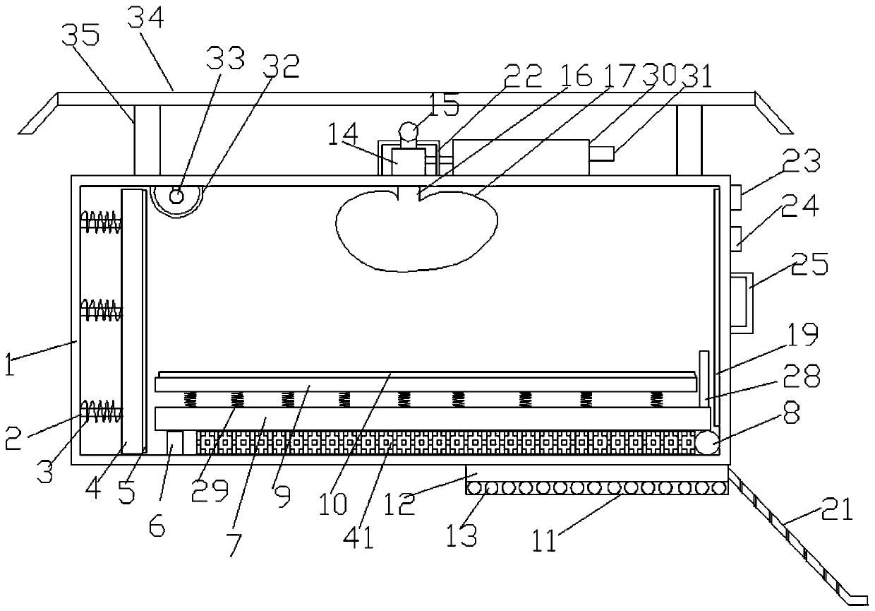
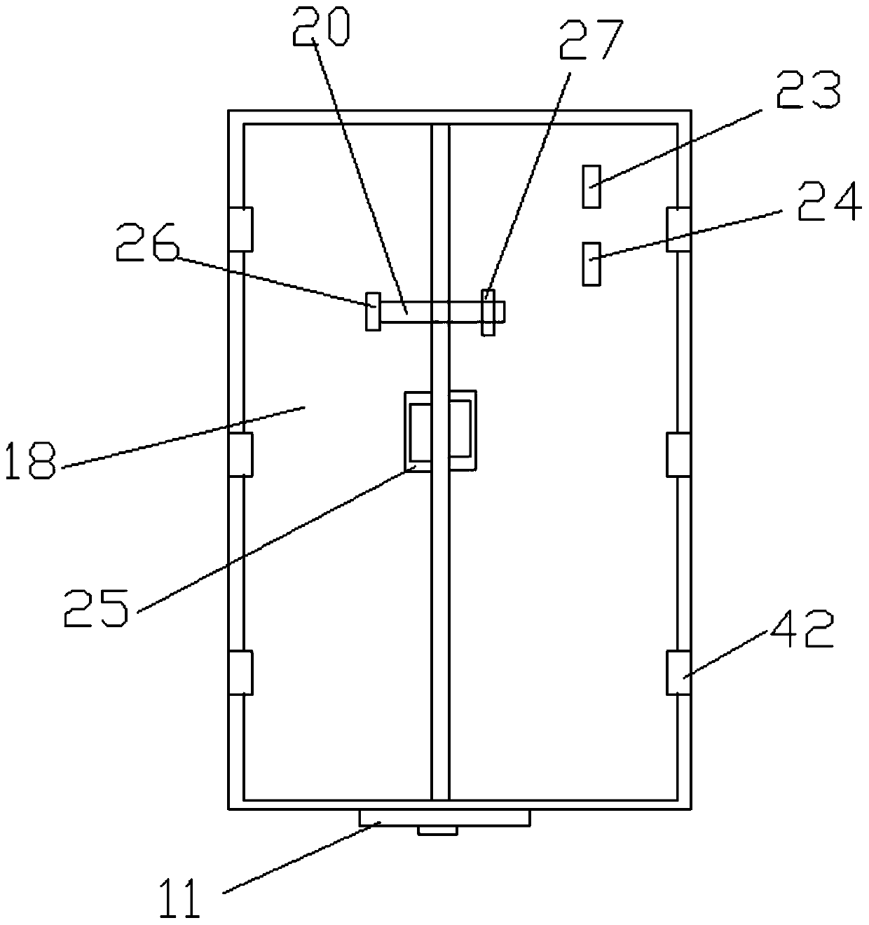
[0023] Such as Figure 1-2 As shown, a controller motor vehicle transportation device according to an embodiment of the present invention includes a carriage 1, a telescopic rod 2 is provided on one side of the inner wall of the carriage 1, and a spring 3 is provided outside the telescopic rod 2, and the telescopic rod 2 The side of the rod ...
PUM
Abstract
The invention discloses a controller motor-vehicle transporting device. The controller motor-vehicle transporting device comprises a carriage; stretchable rods are arranged on one side of the inner wall of the carriage, first springs are arranged outside the stretchable rods, a first baffle is arranged on the side, away from the inner wall of the carriage, of one sides of the stretchable rods, a first rubber plate is arranged on the side, away from the stretchable rods, of one side of the first baffle, a hydraulic stretchable column is arranged on the side, close to the first baffle, of one side of the bottom end inside the carriage, a first fixed plate is arranged at the top end of the hydraulic stretchable column, the side, away from the hydraulic stretchable column, of one side of the bottom end of the first fixed plate is connected with the bottom end inside the carriage through a rotating shaft, a second padding plate is arranged at the portion, between the hydraulic stretchable column and the rotating shaft, of the bottom end inside the carriage, a second fixed plate is arranged on the first fixed plate, and a third rubber plate is arranged at the top end of the second fixedplate; a ladder shell is arranged on the side, close to the rotating shaft, of one side of the bottom end of the carriage, a groove is formed in the top end inside the ladder shell, rolling shafts arearranged at the portions, located at the bottom end of the groove, of the bottom end inside the ladder shell, and a fixed block is arranged on the side, away from the carriage, of one side of the bottom end of the ladder shell.
Description
Technical field [0001] The invention relates to the field of transportation technology, and in particular to a controller motor vehicle transportation device. Background technique [0002] The controller is a master device that controls the start, speed, brake and reverse of the motor by changing the wiring of the main circuit or the control circuit and changing the resistance value in the circuit according to a predetermined sequence. The electronic controller contains many electronic components. When the controller is produced in the workshop, it often needs to be transported to other places for storage or use. When the controller is transported, some electronic components in the controller will fall, which will damage the controller and cause economic losses. In addition, the shipping box is often not full during transportation. When bumps are encountered, the controller is prone to collision, which will produce more defective products. Therefore, it is urgent to develop a con...
Claims
Application Information
Patent Timeline
Application Date:The date an application was filed.
Publication Date:The date a patent or application was officially published.
First Publication Date:The earliest publication date of a patent with the same application number.
Issue Date:Publication date of the patent grant document.
PCT Entry Date:The Entry date of PCT National Phase.
Estimated Expiry Date:The statutory expiry date of a patent right according to the Patent Law, and it is the longest term of protection that the patent right can achieve without the termination of the patent right due to other reasons(Term extension factor has been taken into account ).
Invalid Date:Actual expiry date is based on effective date or publication date of legal transaction data of invalid patent.