
Automatic parking control method and automatic parking system

A technology of automatic parking and control method, applied in the direction of control device, vehicle components, driver input parameters, etc., can solve problems such as increasing user complaints, insufficient system power torque, inability to adjust system power torque, etc., to improve parking efficiency. , the effect of improving the user experience

Active Publication Date: 2020-12-15
WM MOTOR TECH GRP CO LTD
View PDF7 Cites 0 Cited by
  • Summary
  • Abstract
  • Description
  • Claims
  • Application Information

AI Technical Summary

Problems solved by technology

However, in some special scenarios with small obstacles that cannot be detected by ultrasonic probes, but can meet the system calibration parameters, such as special parking spaces with steps, pits, or slopes, limited by ultrasonic detection range, detection blind area, etc. Due to the characteristic defects of the detection technology itself, the existing automatic parking system cannot properly adjust the power torque of the system according to these small obstacles that cannot be detected
For example, some vehicles with front-wheel drive models are prone to insufficient system power torque in this special scene, and cannot cross steps, pits or ramps, resulting in the situation that the vehicle cannot be parked in the parking space many times, which greatly reduces the user experience. sense, increasing user complaints
[0005] Therefore, there is an urgent need for an automatic parking system and a control method suitable for the system, which can overcome the above-mentioned problem of insufficient power torque in special scenarios

Method used

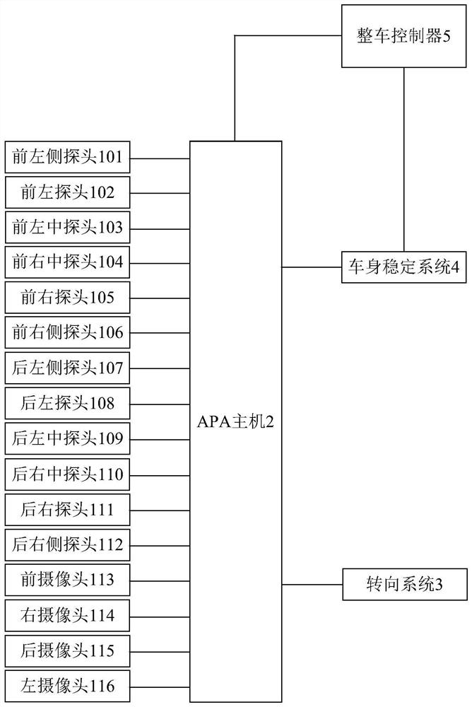
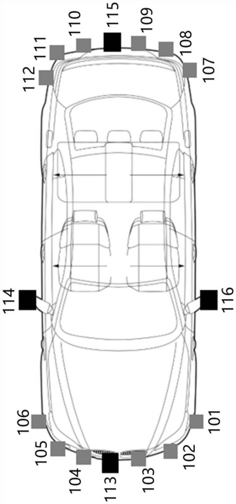

Image

  • Automatic parking control method and automatic parking system
  • Automatic parking control method and automatic parking system
  • Automatic parking control method and automatic parking system

Examples


Embodiment Construction

[0057]The implementation of the present invention will be illustrated by specific specific examples below, and those skilled in the art can easily understand other advantages and effects of the present invention from the content disclosed in this specification. Although the description of the invention will be presented in conjunction with a preferred embodiment, it is not intended that the features of the invention be limited to that embodiment only. On the contrary, the purpose of introducing the invention in conjunction with the embodiments is to cover other options or modifications that may be extended based on the claims of the present invention. The following description contains numerous specific details in order to provide a thorough understanding of the present invention. The invention may also be practiced without these details. Also, some specific details will be omitted from the description in order to avoid obscuring or obscuring the gist of the present invention...


PUM


Abstract

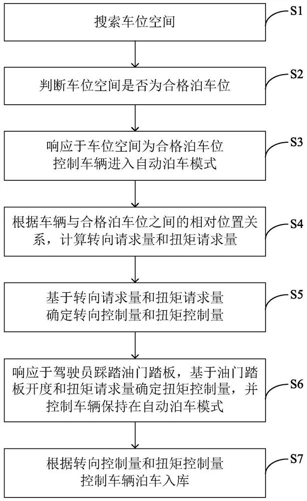
The invention relates to the technical field of automatic parking, and particularly discloses a control method for automatic parking and an automatic parking system. The method comprises the steps ofsearching for a stall space; judging whether or not the stall space is a qualified parking space; controlling a vehicle to enter an automatic parking mode in response to the fact that the stall spaceis the qualified parking space, calculating steering request amount and torque request amount according to a relative position relation between the vehicle and the qualified parking space, determiningsteering control amount and torque control amount based on the steering request amount and the torque request amount, and controlling the vehicle to be parked into a garage according to the steeringcontrol amount and the torque control amount; under the automatic parking mode, determining the torque control amount based on accelerator pedal opening degree and the torque request amount in response to the fact that a driver treads an accelerator pedal, and controlling the vehicle to be maintained in the automatic parking mode. According to the control method for automatic parking and the automatic parking system, a strategy for allowing the driver to tread the accelerator pedal when the vehicle is driven into the garage is adopted, torque is increased to the vehicle in a special scene, andthus parking is smoothly completed.

Description

technical field [0001] The invention relates to the technical field of automatic parking, in particular to an automatic parking control method and an automatic parking system. Background technique [0002] With the gradual increase in the number of cars and the increasingly tight parking spaces, it has become an essential skill for drivers to drive cars into the narrow spaces of various terrains. As a new technology that provides convenience to drivers, the automatic parking system has been applied to their vehicles by a large number of automobile manufacturers. [0003] Existing automatic parking technical solutions are mainly divided into two technical solutions based on ultrasonic detection technology and image recognition detection technology. However, cameras based on image recognition and detection technology only rely on visual detection, and are greatly affected by weather conditions and lighting conditions around the vehicle. For example, in the dark or in severe w...

Claims


Application Information

Patent Timeline
Patent Type & Authority Patents(China)
IPC IPC(8): B60W30/06B60W10/06B60W10/20
CPCB60W10/06B60W10/20B60W30/06B60W2540/10B60W2710/0666B60W2710/20
Inventor 张芳张光荣
Owner WM MOTOR TECH GRP CO LTD
Learn More