
Dynamic path planning method under vehicle networking condition

A technology of dynamic routing and Internet of Vehicles, which is applied in the field of vehicle intelligent driving and active safety. It can solve the problems that the lane-changing model machinery and artificial potential energy field method cannot solve the local minimum point and cannot satisfy the lane-changing scene, etc., and achieve the goal of preventing collisions. Effect

Active Publication Date: 2019-03-22
JIANGSU UNIV
View PDF8 Cites 28 Cited by
  • Summary
  • Abstract
  • Description
  • Claims
  • Application Information

AI Technical Summary

Problems solved by technology

The artificial potential energy field method cannot solve the problems of local minimum points, unreachable targets, etc. It is only suitable for special scenarios and cannot meet the lane-changing scenarios in most cases.
Local path planning based on polynomials can satisfy the scenario where there is only one stationary vehicle ahead when changing lanes, but does not consider the influence of other vehicle state changes on lane changing during the entire lane changing process
The existing research on the lane change trajectory based on the spline method is only calculated at the starting point of the lane change, and cannot guarantee the safety of the entire lane change process.
At present, the research on static path planning is mainly aimed at two vehicles driving on the same straight lane with a heading angle of zero, ignoring the influence of environmental conditions, and the practicability is not high; currently, dynamic path planning mainly relies on empirical formulas, and it is difficult to obtain the optimal path. Lane Change Model Comparison Mechanical

Method used


Image

  • Dynamic path planning method under vehicle networking condition
  • Dynamic path planning method under vehicle networking condition
  • Dynamic path planning method under vehicle networking condition

Examples


Embodiment Construction

[0057] The specific embodiments of the present invention will be described in conjunction with the accompanying drawings, so that future researchers can better understand the present invention.

[0058] Implementation process of the present invention

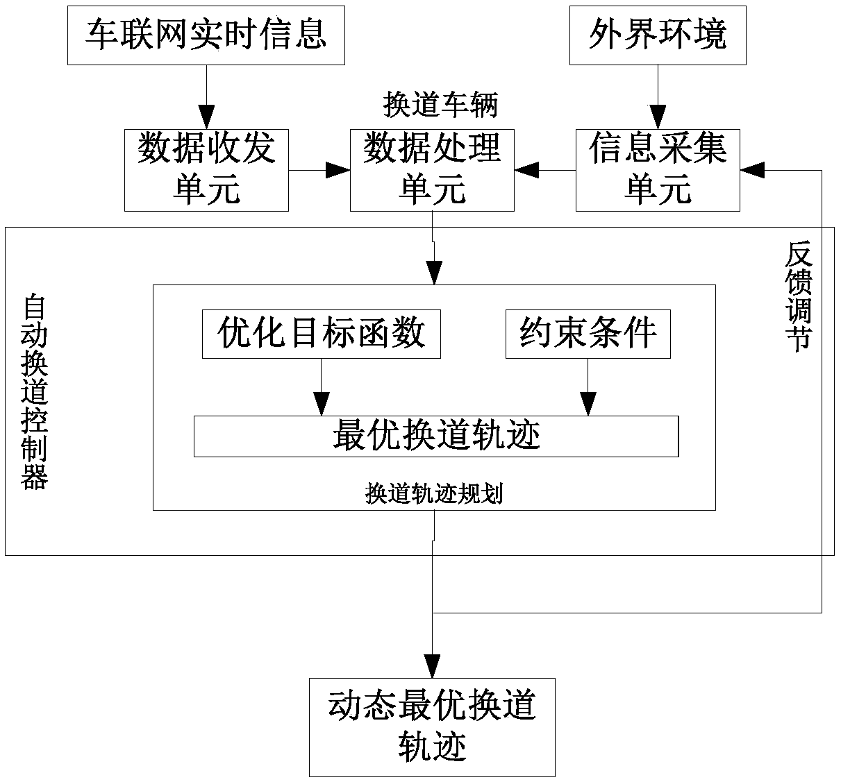
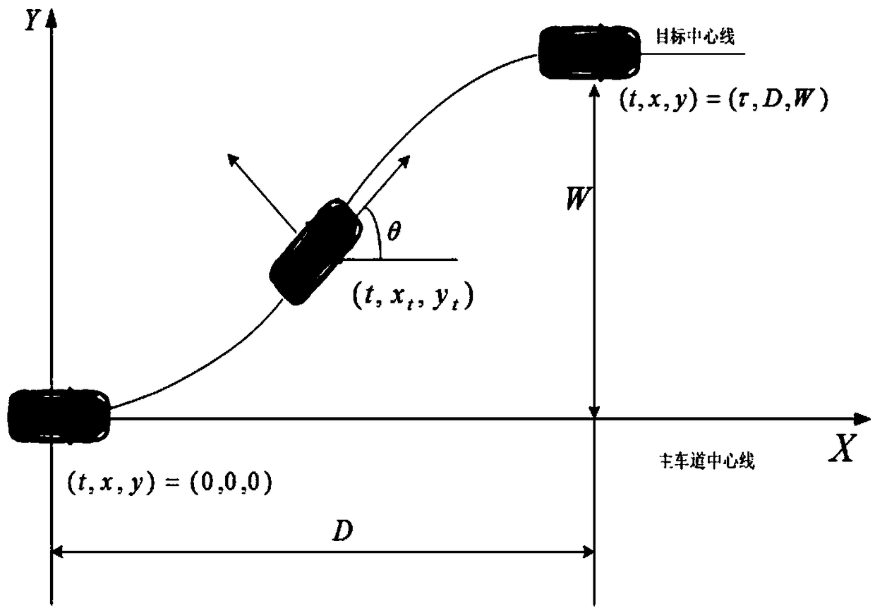
[0059] The present invention is based on a dynamic path planning method under the condition of the Internet of Vehicles. The intelligent vehicle of the Internet of Vehicles uses the Internet of Vehicles and sensors to sense the driving environment. The sensors include GPS, millimeter wave radar, camera and laser radar to obtain the surrounding environment information of the vehicle. These raw data Fusion is carried out in the "sensor data fusion module", and at the same time, the vehicle networking transceiver unit receives the real-time information of the vehicle network to obtain dynamic and static obstacle information. According to the real-time information, the automatic lane change controller selects different constraints a...


PUM


Abstract

The invention discloses a dynamic path planning method under a vehicle networking condition, which adopts the following steps: the planning of a dynamic lane changing track is carried out by constructing a target function of comprehensive lane changing time and maximum acceleration for improving comfort and passing efficiency, utilizing a cubic spline method, the constraint condition and the target function solve the optimal lane changing track and referring to the lane changing track according to the real-time information provided by a vehicle networking, feeding back the real-time updating of the data to a decision-making unit in time for re-planning the path when a sudden situation occurs in the front so as to prevent collision, so that the lane changing vehicle can adapt to the motionstate change of the surrounding vehicle. According to the dynamic path planning method under the vehicle networking condition, the planned track equation is determined by introducing the target function and from the aspect of an optimal solution, and the dynamic path planning method under the vehicle networking condition has the advantages of safety, comfort and high efficiency in the aspects of reducing lane change time and preventing collision.

Description

technical field [0001] The invention relates to the technical field of vehicle intelligent driving and active safety, in particular to a dynamic path planning method based on the Internet of Vehicles condition. Background technique [0002] Road accidents are usually caused by some non-standard driving behaviors of drivers, and road accidents caused by lane changing process account for about 23% of the total number of traffic accidents caused by improper driver operations. Therefore, making up for the lack of consideration of the changes in the state of motion of surrounding vehicles and the comfort and efficiency of existing vehicles when automatically changing lanes, and planning a safe and reasonable road to prevent collisions will help reduce the occurrence of road accidents and improve the quality of motor vehicles. The safety level of road driving is of great significance. [0003] At present, the lane-changing path is designed based on the trapezoidal acceleration pr...

Claims


Application Information

Patent Timeline
Patent Type & Authority Applications(China)
IPC IPC(8): B60W30/08B60W40/00B60W40/10B60W40/105
CPCB60W30/08B60W40/00B60W40/10B60W40/105
Inventor 刘志强张腾
Owner JIANGSU UNIV
Learn More