
Cotton and linen cloth drying equipment

A cloth drying, cotton linen technology, applied in the direction of drying, dryers, lighting and heating equipment, etc., can solve the problems of large space occupied by equipment, affect the dyeing effect of fabrics, and reduce the drying efficiency of equipment. The space is small, the effect of improving heat transfer, and the effect of fast speed

Active Publication Date: 2019-03-22
SHAOXING UNIVERSITY
View PDF5 Cites 5 Cited by
  • Summary
  • Abstract
  • Description
  • Claims
  • Application Information

AI Technical Summary

Problems solved by technology

[0004] In the above-mentioned documents, the hot air circulation is used to recycle heat in the box. Although it can effectively improve the utilization rate of heat, it has a slow drying speed. If it is necessary to completely dry the fabric, the drying equipment is large in size. In the industry, the equipment takes up a lot of space. Obviously, in industrial printing and dyeing, it has a huge impact on the arrangement of various equipment in the entire factory area; and because of the heat Reuse and recycle, then the water vapor after drying will re-enter the oven. When the water vapor in the oven reaches a large amount, on the one hand, it will cause the drying efficiency of the equipment to decrease, and the water vapor on the subsequent fabric will Volatilization is affected. In the subsequent drying process, the cloth cannot achieve a complete drying effect. During drying, as the drying amount of the cloth increases, the drying effect will gradually decrease; on the other hand, when When the water vapor in the oven is too large, the water vapor will gather and fall on the fabric, because the fabric contains pigments, some of the pigments will still dissolve, and the fabric after drying will form relatively small spots, causing the original dyeing After the uniform fabric is dried, the fabric will still be dyed unevenly, which seriously affects the dyeing effect of the fabric

Method used


Image

  • Cotton and linen cloth drying equipment
  • Cotton and linen cloth drying equipment
  • Cotton and linen cloth drying equipment

Examples


Embodiment Construction

[0040] In order to enable those skilled in the art to better understand the solutions of the present invention, the technical solutions in the embodiments of the present invention will be clearly and completely described below in conjunction with the drawings in the embodiments of the present invention.

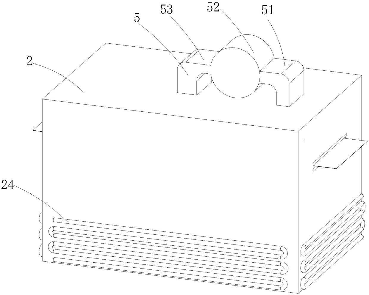
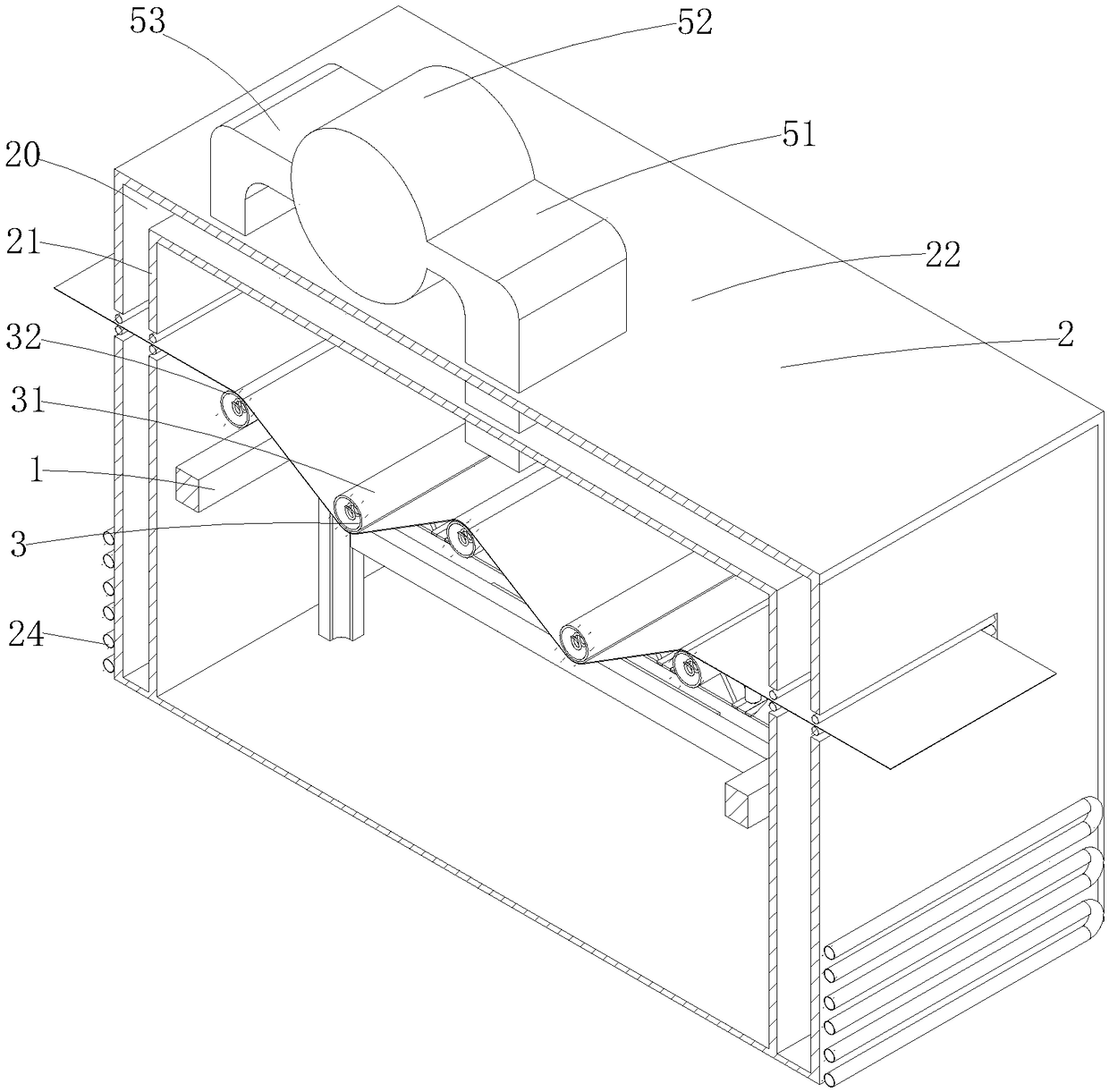
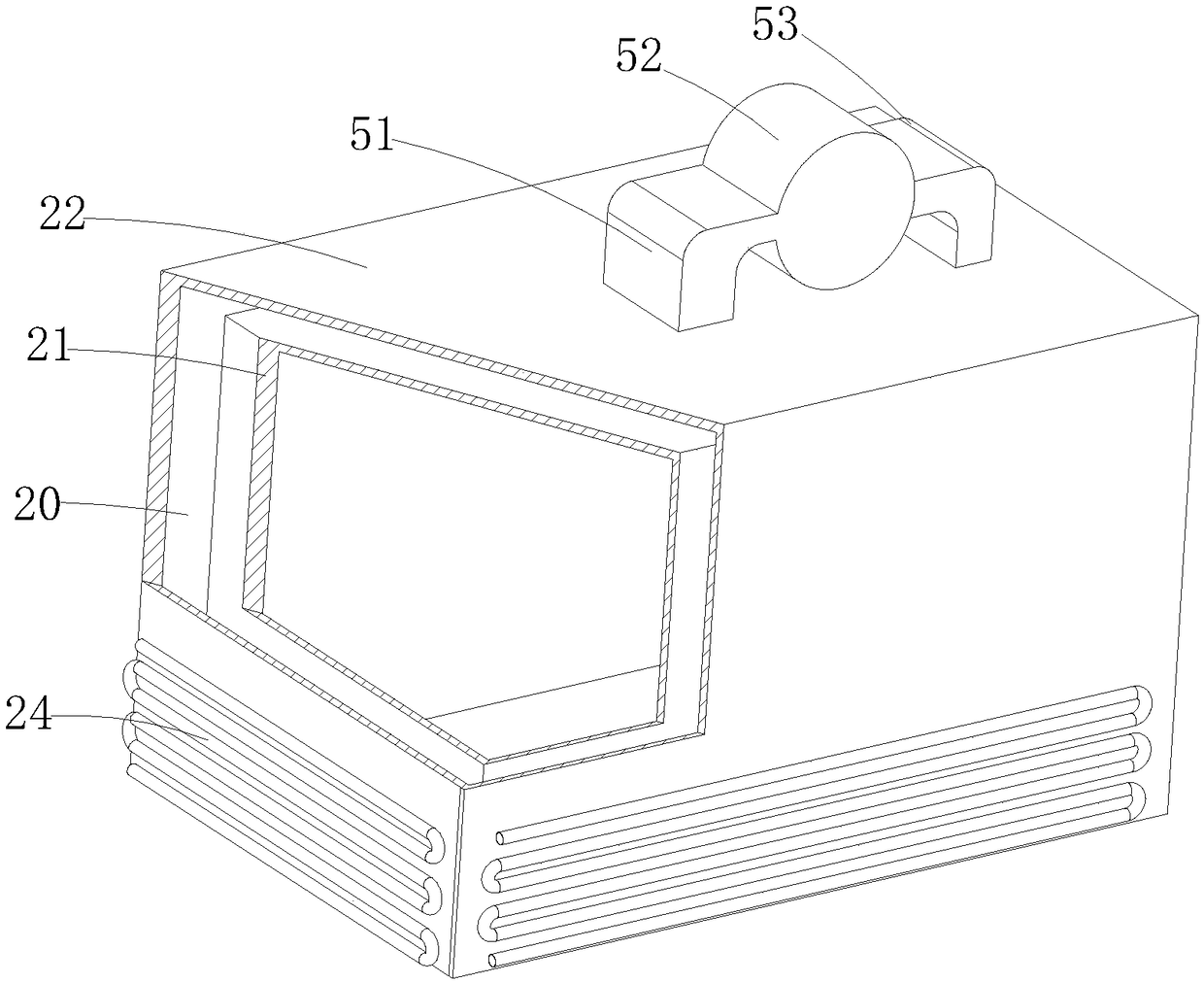
[0041] Such as Figure 1-18 As shown, a cotton and linen drying equipment, a frame 1, a box body 2, a drying roller structure 3, a heating structure 4 and a dehumidification structure 5, wherein the frame 1 is a metal frame, and the box body 2 Covered in the frame 1, the drying roller structure 3 is arranged on the frame 1, the drying roller structure 3 is used to be in contact with the cotton and linen cloth, and will dry the clothes Stretch the cloth to increase the holes on the cloth. Specifically, the drying roller structure 3 includes a plurality of first roller bodies 31, a plurality of second roller bodies 32 and a driving part 33; specifically, the The first roller b...


PUM


Abstract

The invention discloses cotton and linen cloth drying equipment. The cotton and linen cloth drying equipment comprises a frame, a box body covering the frame, a drying roller structure for contactingwith wet cotton and linen cloth and stretching the cotton and linen cloth to open holes in the cotton and linen cloth during drying the cloth, a heating structure for increasing the temperature of thedrying roller structure, and a dehumidifying structure for absorbing water vapor in an oven and heating the inner wall of the box body by the absorbed water vapor. As the drying roller structure is directly contacted with the cloth, when the cloth is dried, the temperature of the cloth can be quickly transferred to the cloth, the cloth is fast in heating, and the drying efficiency is high.

Description

technical field [0001] The invention belongs to the technical field of textile drying, in particular to a cotton and linen drying equipment. Background technique [0002] In the process of textile printing and dyeing, the cloth needs to be dried after being bleached and dip-dyed. Most of the existing cloth drying is carried out by blowing hot air into the oven, but this drying method, The speed of heat transfer is slow, the drying efficiency is low, the energy consumption is large, and the economic benefit is poor. [0003] Chinese patent CN104713336B discloses an oven for a cloth dryer, which includes a box body. The left side panel of the box body has a material inlet, the right side panel of the box body has a discharge port, and the top plate of the box body is fixed. Air fan, the intake fan is fixed on the bottom plate of the box body, the outlet end of the intake fan is connected with the air inlet hole on the bottom plate of the box body, the air inlet of the exhaust...

Claims


Application Information

Patent Timeline
IPC IPC(8): F26B13/08F26B23/00F26B25/22
CPCF26B13/08F26B23/00F26B25/22
Inventor 卢丽娟张新华王秀庆潘露丹何绍木陈坤
Owner SHAOXING UNIVERSITY
Learn More