Fabric insulation performance tester under motion state
A technology of thermal insulation performance and motion state, applied in the field of textile measurement and dynamic tester for thermal insulation performance of fabrics, can solve the problems of inability to test the dynamic thermal insulation performance of fabrics, single testing environment, etc., and achieves improved testing efficiency, high mechanical strength, and good performance. Effect
- Summary
- Abstract
- Description
- Claims
- Application Information
AI Technical Summary
Problems solved by technology
Method used
Image
Examples
Embodiment 1
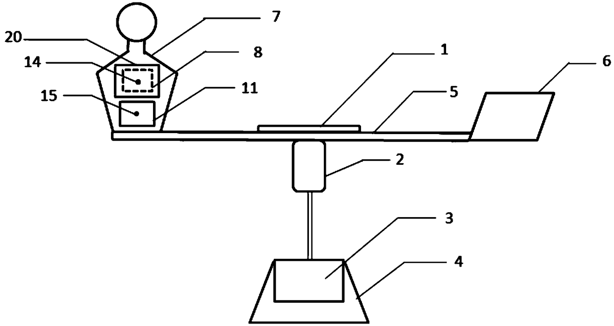
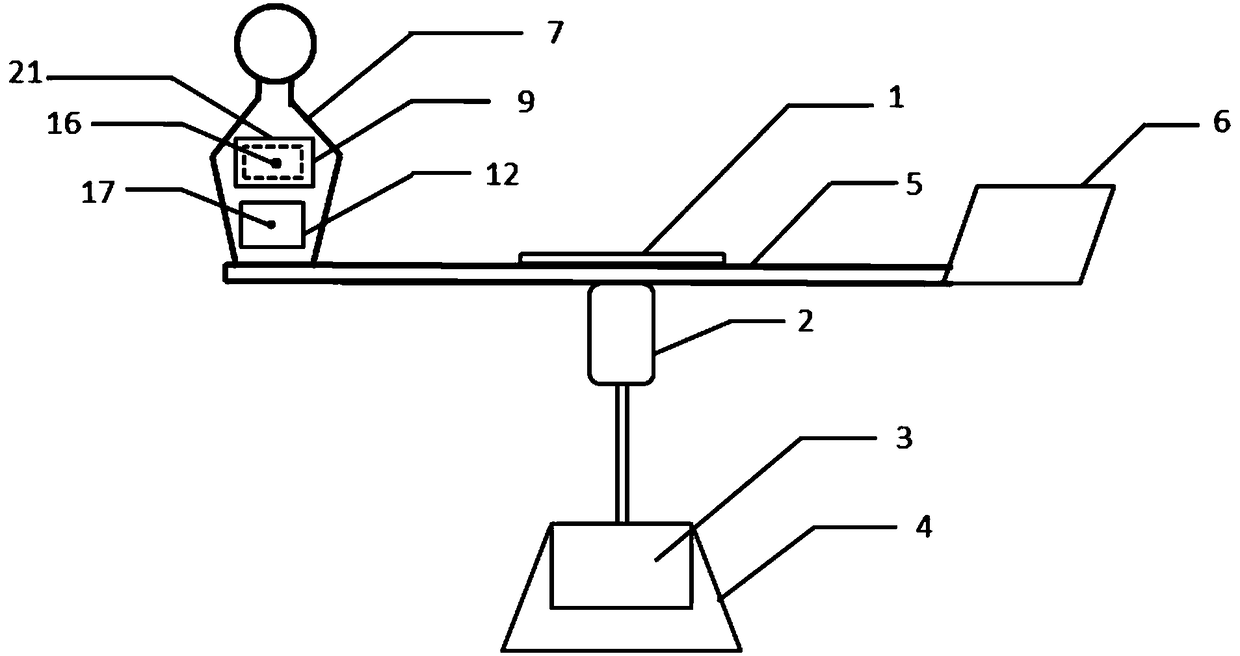
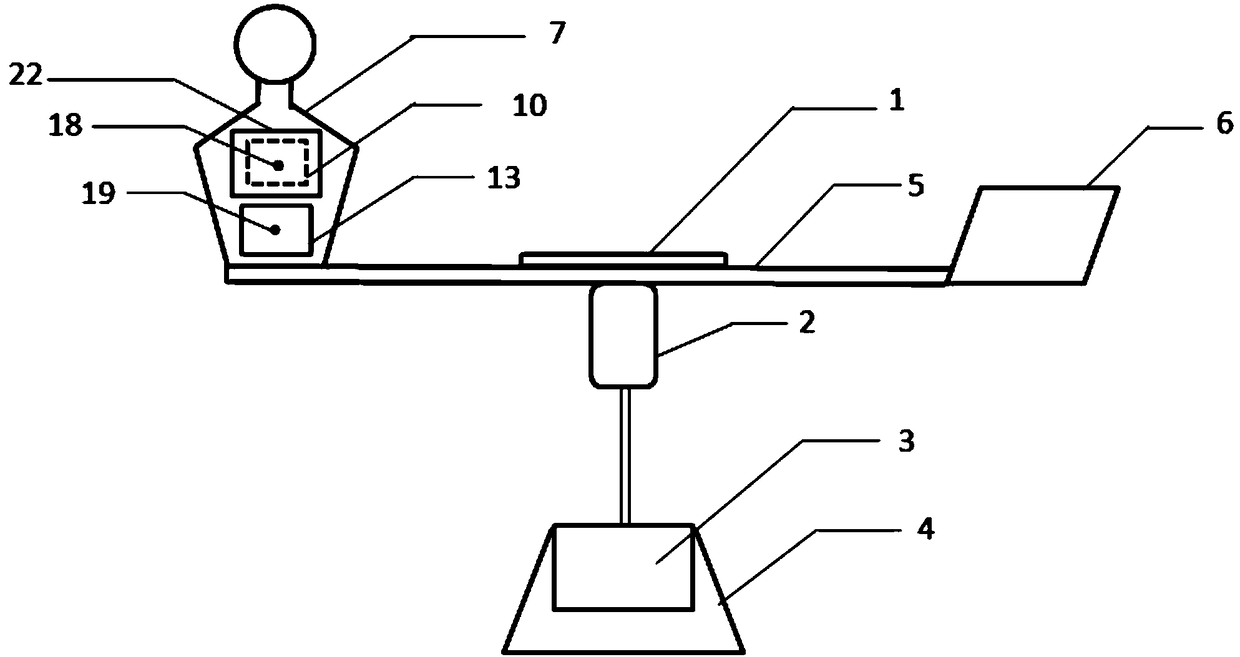
[0044] Such as Figure 1-3 Shown is the form of the fabric thermal insulation property tester under a kind of motion state provided by this method, and this tester contains three heating plates (11, 12, 13) for comparison, specifically, the tester provided by the present invention includes dynamic Simulator, described dynamic simulator is made of base (4), control board (1), reduction motor (3), crossbeam (5), counterweight plate (6), mannequin (7), the first test heating Plate (8), heating plate (9) for the second test, heating plate (10) for the third test, temperature sensor.
[0045] The deceleration motor (3) is connected to an external power supply and fixed inside the base (4). The speed setting range is from 10 to 1000 revolutions per minute. The purpose is to simulate different environmental wind speeds by changing the speed, so as to study and test the fabric under different conditions. The main shaft of the geared motor is fixedly connected to the connector (2), an...
Embodiment 2
[0048] The fabrics to be tested (20, 21, 22) are woven cotton fabrics, and three identical samples of the fabrics to be tested are covered on the heating plate (8, 9, 10) for testing, and the three temperature sensors (14, 16, 18) Install on the surface of the heating plate for testing respectively, then place the temperature sensors (15, 17, 19) respectively on the control heating plates (11, 12, 13), adjust the sensor to the connecting point between the connecting head 2 and the crossbeam. The distance is 150mm, turn on the power switch of the control board 1, set the data analysis and display system to the receiving state, set the test heating plates (8, 9, 10) through the data analysis and display system control board on the PC, and control the heating plate The initial temperature of (11, 12, 13) is 37 degrees Celsius to simulate the normal body temperature of the human body. Set the speed of the geared motor 3 to 30 revolutions per minute, and set the running time to 600 ...
Embodiment 3
[0050] The fabrics to be tested (20, 21, 22) are knitted cotton fabrics, three identical samples of the fabric to be tested are covered on the heating plate (8, 9, 10) for testing, and the three temperature sensors (14, 16, 18 ) are respectively installed on the surface of the heating plate for testing, and then temperature sensors (15, 17, 19) are respectively placed on the control heating plate (11, 12, 13), and the distance between the sensor and the connecting point between the connecting head 2 and the beam is adjusted 150mm, turn on the power switch of the control board 1, set the data analysis and display system to the receiving state, set the test heating plates (8, 9, 10) through the data analysis and display system control board on the PC, and the control heating plate ( The initial temperature of 11, 12, 13) is 37 degrees Celsius to simulate the normal body temperature of the human body. Set the speed of the geared motor 3 to 30 revolutions per minute, and set the ru...
PUM
 Abstract
Description
Claims
Application Information
 - R&D
- Intellectual Property
- Life Sciences
- Materials
- Tech Scout
- Unparalleled Data Quality
- Higher Quality Content
- 60% Fewer Hallucinations
Browse by: Latest US Patents, China's latest patents, Technical Efficacy Thesaurus, Application Domain, Technology Topic, Popular Technical Reports.
© 2025 PatSnap. All rights reserved.Legal|Privacy policy|Modern Slavery Act Transparency Statement|Sitemap|About US| Contact US: help@patsnap.com


