Virtual image display device

A virtual image display device and technology for displaying images, applied in optics, magnifiers, instruments, etc., can solve problems such as influencing and difficult to configure the image quality of lenses, and achieve the effect of narrowing the configuration between the left and right lenses

Active Publication Date: 2019-03-22
SEIKO EPSON CORP
View PDF9 Cites 0 Cited by
  • Summary
  • Abstract
  • Description
  • Claims
  • Application Information

AI Technical Summary

Problems solved by technology

In addition, it may be difficult to arrange a lens suitable for a person's face due to the enlargement of the lens, or it may affect the image quality.

Method used


Image

  • Virtual image display device
  • Virtual image display device
  • Virtual image display device

Examples


no. 1 approach 〕

[0040] Below, refer to figure 1 etc., the virtual image display device according to the first embodiment of the present invention will be described in detail.

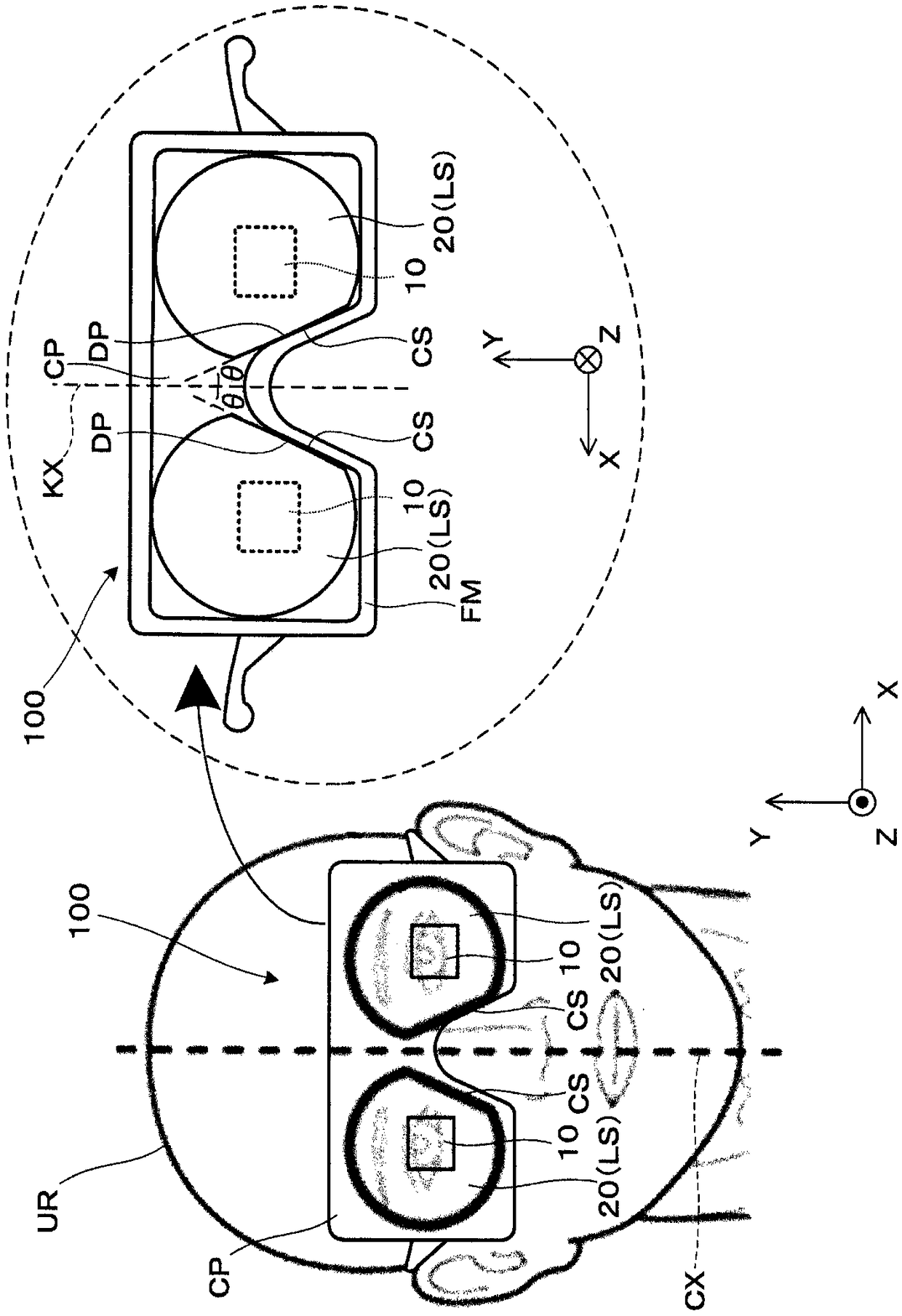
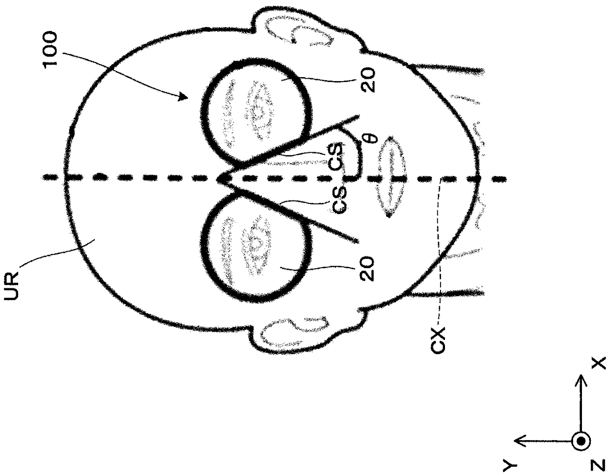
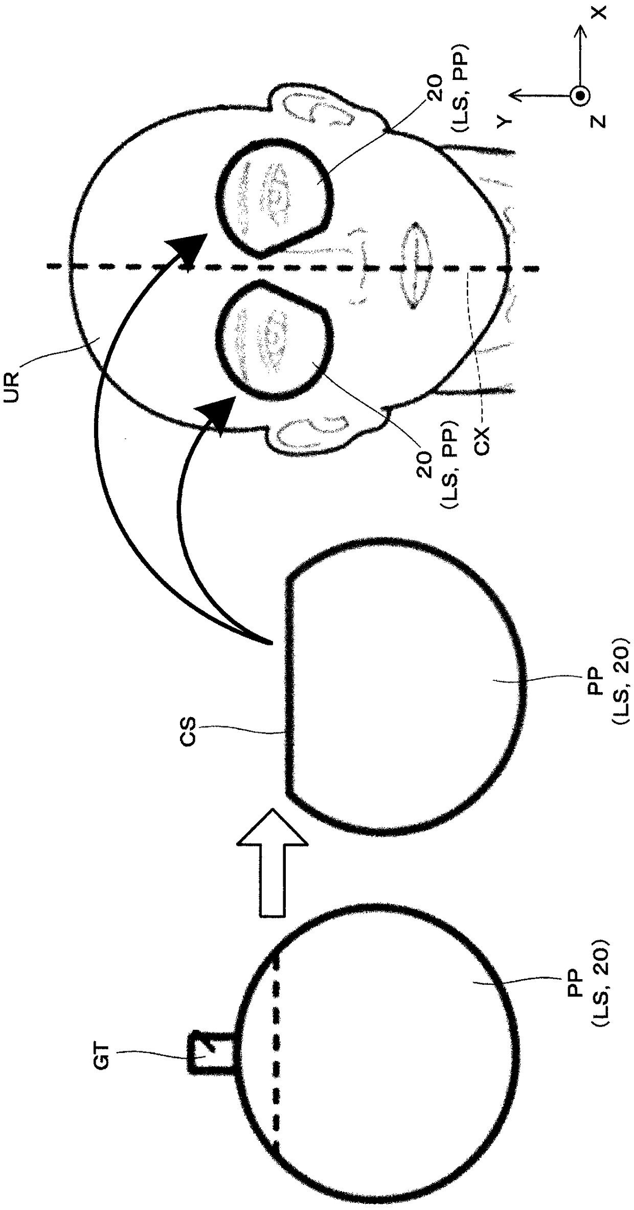
[0041] Such as figure 1 or Figure 4 As shown schematically, the virtual image display device 100 of this embodiment is a virtual image display device as follows, that is, a head-mounted display (HMD): it has an image display device 10 as an image element (image display unit) and an enlarging optical system 20, and The viewer or user wearing the virtual image display device 100 can visually recognize the image light (image light) formed by the virtual image. Such as figure 1 As shown, the image display device 10 and the magnification optical system 20 are accommodated and protected by the exterior part CP. here, as Figure 4 etc., in the virtual image display device 100 of this embodiment, the optical axis AX of the optical system is in the Z direction. In addition, it is assumed that the horizontal direction of ...

no. 2 approach 〕

[0069] Below, refer to Figure 10 , the virtual image display device according to the second embodiment will be described. The virtual image display device of the present embodiment differs from the first embodiment in which a lens, which is a main part of the magnification optical system, is composed of a plurality of lenses. In addition, the appearance structure and the assembly of the magnifying optical system are the same as those of the first embodiment (refer to figure 1 ) are the same, so illustrations and descriptions are omitted.

[0070] The virtual image display device 200 of the present embodiment includes an image display device 210 as a video element, and an enlarging optical system 220 .

[0071] The image display device 210 has: a panel section 11 as a main main body, which performs image formation; a polarizing plate 12, which extracts components of linearly polarized light; and a first 1 / 4 wavelength plate (λ / 4 plate) 13, which makes The components passing...


PUM


Abstract

Provided is a virtual image display device that makes it possible to achieve a reduction in size or a reduction in weight of the device which has a trend to become large, while considering influence on the image quality or fitting of the device to a human face. By removing part of a lens effective diameter range in a cut lens (LS), a lens is reduced in size and weight in an HMD that trends towarda larger device size. At this time, by making an area to be removed within the lens effective diameter range to be an area on a nose side, reductions in size and weight can be achieved while considering influence on image quality or fitting to a human face.

Description

technical field [0001] The present invention relates to a virtual image display device which is worn on the head and presents images formed by image elements and the like to observers. Background technique [0002] In recent years, in virtual image display devices (or head-mounted display devices) such as head-mounted displays (hereinafter also referred to as HMDs) worn on the observer's head, widening the viewing angle has been developed. In order to cope with the widening of the field of view, the diameter and wall thickness of the lens are generally increased, but HMDs are also required to be small and lightweight. In addition, it may be difficult to dispose a lens suitable for a person's face due to the enlargement of the lens, or it may affect the image quality. [0003] For example, the optical design of HMDs is known in consideration of optical axes of display elements and lenses for display quality improvement (Patent Document 1), but it is unclear whether lens shap...

Claims


Application Information

Patent Timeline
Patent Type & Authority Applications(China)
IPC IPC(8): G02B27/01
CPCG02B27/0172G02B2027/0178G02B17/0856G02B17/086G02B25/001G02B27/286G02B5/3083G02B27/0955G02B27/0977
Inventor 宫尾敏明高木将行武田高司小松朗山口论人
Owner SEIKO EPSON CORP
Why Eureka
Try Eureka