Power conversion device and wind power generation system

A technology of power conversion device and wind power generation system, which is applied in the direction of wind power generation, irreversible DC power input conversion to AC power output, etc., which can solve the problem of height increase and achieve the effect of improving maintenance workability

Inactive Publication Date: 2019-03-08
HITACHI LTD
View PDF1 Cites 0 Cited by
  • Summary
  • Abstract
  • Description
  • Claims
  • Application Information

AI Technical Summary

Problems solved by technology

[0004] When the generator output and power transmission voltage are increased in this way, gaps are provided to ensure the insulation distance and creepage distance between different potentials, which leads to an increase in the size of the power converter.

Method used


Image

  • Power conversion device and wind power generation system
  • Power conversion device and wind power generation system
  • Power conversion device and wind power generation system

Examples


Embodiment 1

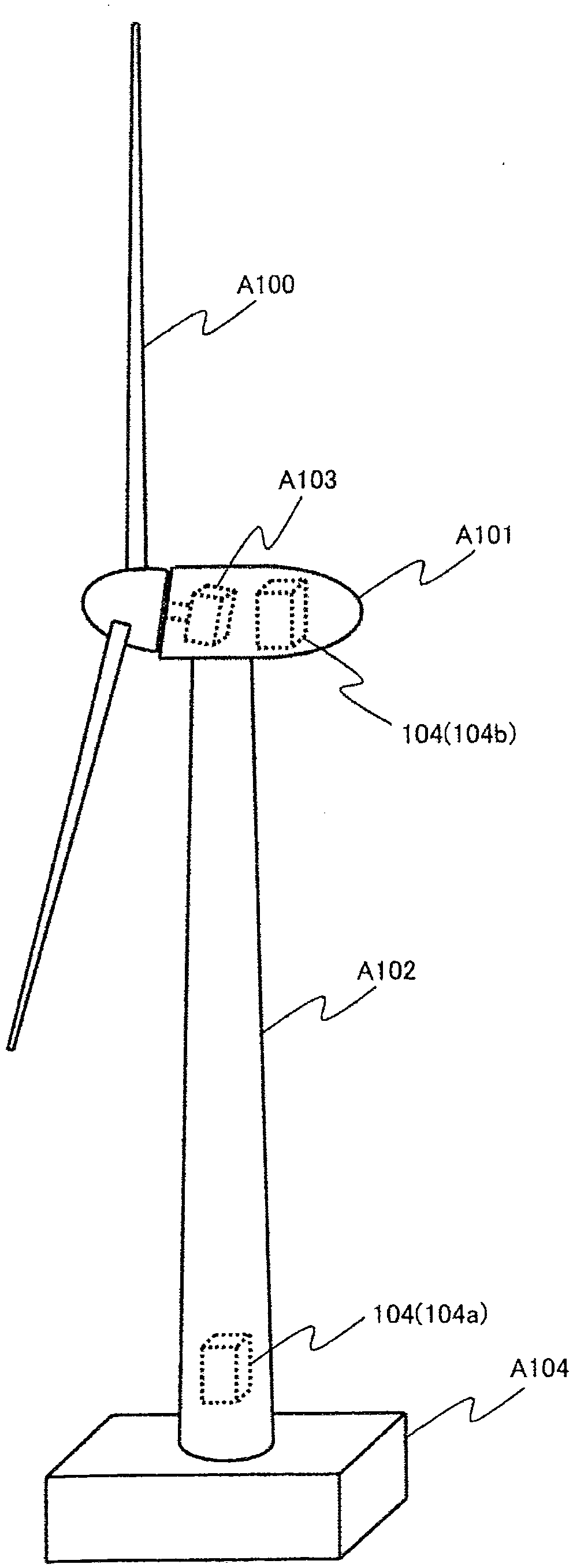
[0028] Hereinafter, an example of application to a wind power generation system will be described. figure 1 A schematic diagram showing a power converter (also referred to as a power conversion device) mounted on a wind power generation facility is shown. The wind power generation equipment is mainly composed of a base (A104), a tower (A102), a dome (A101) and blades (A100), and the generator mounted in the dome (A101) (A103) Power generation. exist figure 1 In the above, the rotating shaft of the blade (A100) is directly connected to the generator (A103), but the same applies to the case where the speed increaser and the gear are mounted on the rotating shaft. During the power generation process of the generator (A103), the rotation of the blades (A100) is dependent on the wind force and the rotational speed fluctuates, so the voltage supplied to the excitation of the generator (A103) or the The output voltage is controlled by power conversion by power converters (104a to ...


PUM


Abstract

In order to ensure an insulation distance and a creepage distance between different voltage levels in a power converter, conventional techniques using air insulation have been causing the power converter to increase in size as an input voltage and an output voltage increase. There has also been a problem that, when the air insulation is changed to oil insulation to reduce the size of the power converter, it becomes difficult to replace components. A power converter is configured by dividing components (a semiconductor element, a smoothing capacitor, a semiconductor element driving circuit, anda wire or a metal conductor plate for connecting each of the components) constituting the power converter, housing the divided components in a plurality of individual boxes filled with an insulatingoil, and connecting the individual boxes with each other. The power converter is housed in a chassis box filled with insulating oil, thereby reducing the size of the power converter. Dividing the power converter into the plurality of individual boxes improves the workability of component replacement.

Description

technical field [0001] The present invention relates to a power conversion device and a wind power generation system, in particular to a main circuit structure (semiconductor element, bus bar, cooler, capacitor, etc.) or a power conversion device suitable for insulation and a wind power generation system. Background technique [0002] In recent years, power converters are often used to control electric motors at variable speeds or to obtain electric power at a constant frequency. In this power converter, in order to reduce conversion efficiency and power transmission loss, it is required to increase generator output and power transmission voltage. [0003] For example, from the viewpoint of increasing the ratio of renewable energy, power generation using natural energy such as sunlight and wind power has attracted attention. ), small and lightweight power converters are required. On the other hand, in order to reduce the number of windmill towers installed, the power gener...

Claims


Application Information

Patent Timeline
Patent Type & Authority Applications(China)
IPC IPC(8): H02M7/48
CPCH02M7/48Y02E10/76
Inventor 小南勉后藤研吾森田裕菊池辉
Owner HITACHI LTD
Why Eureka
Try Eureka