
Heat dissipation temperature control technology for active phased array radar assembly

A technology of phased array radar and components, which is applied in the direction of modification through conduction heat transfer, cooling/ventilation/heating transformation, etc. It can solve the problems of poor temperature consistency, large volume, and high heat flux density of components, etc., to reduce temperature gradients, The effect of strong environmental adaptability and independent heat dissipation structure

Pending Publication Date: 2019-03-22
安徽瞭望科技有限公司
View PDF0 Cites 12 Cited by
  • Summary
  • Abstract
  • Description
  • Claims
  • Application Information

AI Technical Summary

Problems solved by technology

[0003] At present, there are many heat dissipation technologies for a single T / R component, mainly using forced air cooling, liquid cooling, and evaporative cooling. The forced air cooling has limited heat dissipation capacity and poor temperature consistency; Disadvantages such as heavy weight and easy leakage
In the prior art, there are many T / R components in the front structure of the active phased array radar antenna, and all the T / R components are installed together in a tight arrangement, basically there is no gap between the components, and the rear of the components is directly connected to the component control board. Plug-in connection, the distance between them is very small, and the heat flux density of the components is high; the use of ordinary air cooling cannot meet the heat dissipation requirements of the components, and there is no designable installation space for liquid cooling and evaporative cooling

Method used


Image

  • Heat dissipation temperature control technology for active phased array radar assembly
  • Heat dissipation temperature control technology for active phased array radar assembly
  • Heat dissipation temperature control technology for active phased array radar assembly

Examples


Embodiment Construction

[0025] Specific embodiments of the present invention will be described in detail below in conjunction with the accompanying drawings. It should be understood that the specific embodiments described here are only used to illustrate and explain the present invention, and are not intended to limit the present invention.

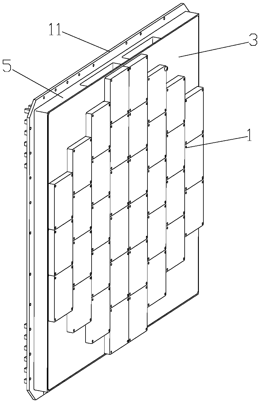
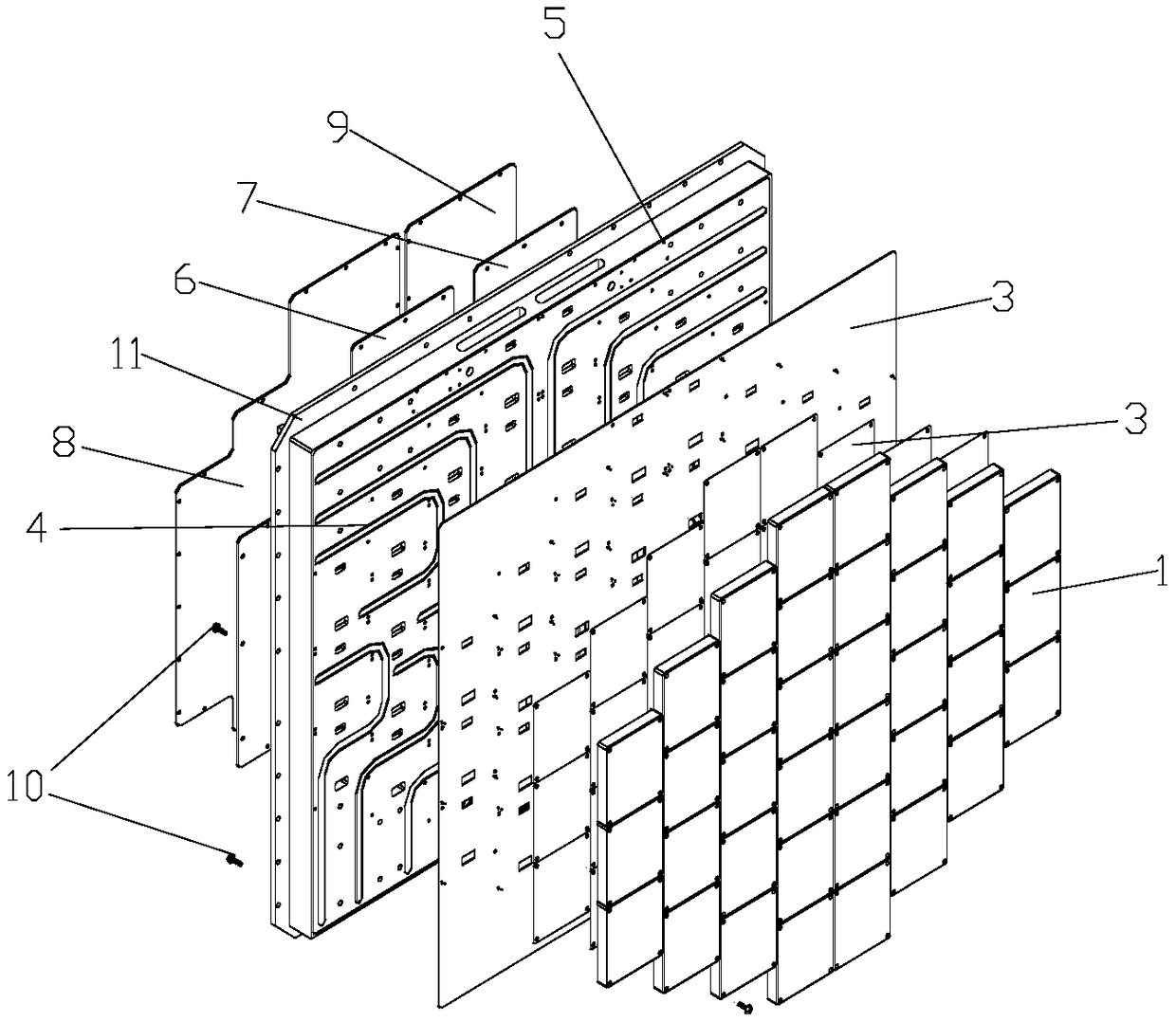
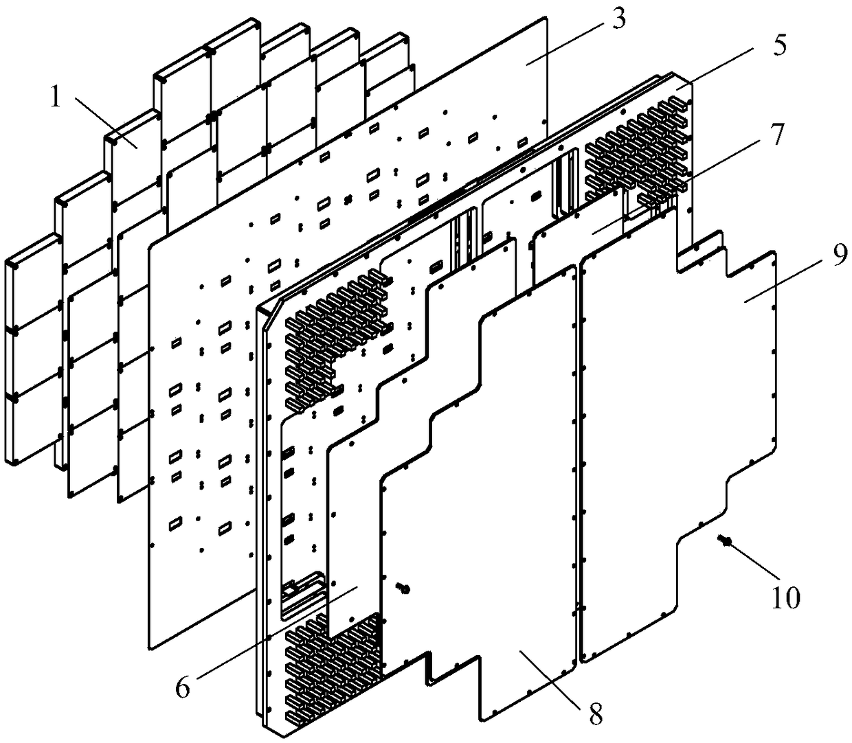
[0026] combined with Figure 1-3 , a heat dissipation and temperature control technology for active phased array radar components, using the "combined thermal control" heat dissipation technology based on the combination of heat pipes, vapor chambers and heat dissipation fins, the multiple T / R components 1 are screwed together 10 are centrally installed on a uniform temperature plate 3, the heat conduction pad 2 is arranged between the temperature uniform plate 3 and the contact surface of the T / R assembly 1, and the temperature uniform plate 3 is welded on the substrate 5 On the side panel of the substrate 5 contacting the temperature chamber 3, there are a pl...


PUM


Abstract

The invention relates to a heat dissipation temperature control technology for an active phased array radar assembly. A plurality of T / R assemblies are installed collectively on one temperature equalization plate by screws; a thermal-conducting gasket is arranged between contact surfaces of the temperature equalization plate and the T / R assemblies; and the temperature equalization plate is weldedto a substrate. A plurality of thermal tubes having different lengths, different shapes and different specifications are arranged on one side panel, in contact with the temperature equalization plate,of the substrate symmetrically; the tails of the plurality of thermal tubes are collected and concentrated at four side corners of the substrate respectively; and cylindrical cooling fins are arranged at four corner areas of the substrate. The heat dissipation temperature control technology has the following beneficial effects: on the basis of the combined thermal-cavity cooling structure of combination of the thermal tubes, the temperature equalization plate, and the cooling fins, the active phased array radar assembly is cooled; the heat dissipation efficiency is high, the temperature uniformity is high, and the reliability is high; and the active phased array radar assembly works normally and continuously.

Description

technical field [0001] The invention belongs to the technical field of heat control, and in particular relates to a heat dissipation and temperature control technology of an active phased array radar component. Background technique [0002] In modern warfare, active phased array radars play an increasingly important role, and various military powers in the world have successively developed various types of active phased array radars. Regardless of the frequency band and purpose, the active phased array radar is mainly composed of T / R components, and an active phased array radar can have as few as several hundred or as many as thousands of T / R components. The T / R component is the core unit of the active phased array radar. The performance of the T / R component is the key to realizing and ensuring the performance of the radar, and the heat dissipation of the T / R component directly affects the T / R performance and work Therefore, the thermal control technology of T / R components ...

Claims


Application Information

Patent Timeline
IPC IPC(8): H05K7/20
CPCH05K7/2039
Inventor 刘联节
Owner 安徽瞭望科技有限公司
Learn More