Method and equipment for conveying and fixing workpiece

A workpiece and equipment technology, applied in the corresponding equipment field, can solve the problems of high investment and high cost

Active Publication Date: 2019-03-26
STROTHMANN MACHINES & HANDLING
View PDF8 Cites 0 Cited by
  • Summary
  • Abstract
  • Description
  • Claims
  • Application Information

AI Technical Summary

Problems solved by technology

At the same time, the possibility of correcting the positioning of several workpieces by means of two positioning devices at the same time, which leads to higher investment and correspondingly high costs

Method used


Image

  • Method and equipment for conveying and fixing workpiece
  • Method and equipment for conveying and fixing workpiece

Examples


Embodiment Construction

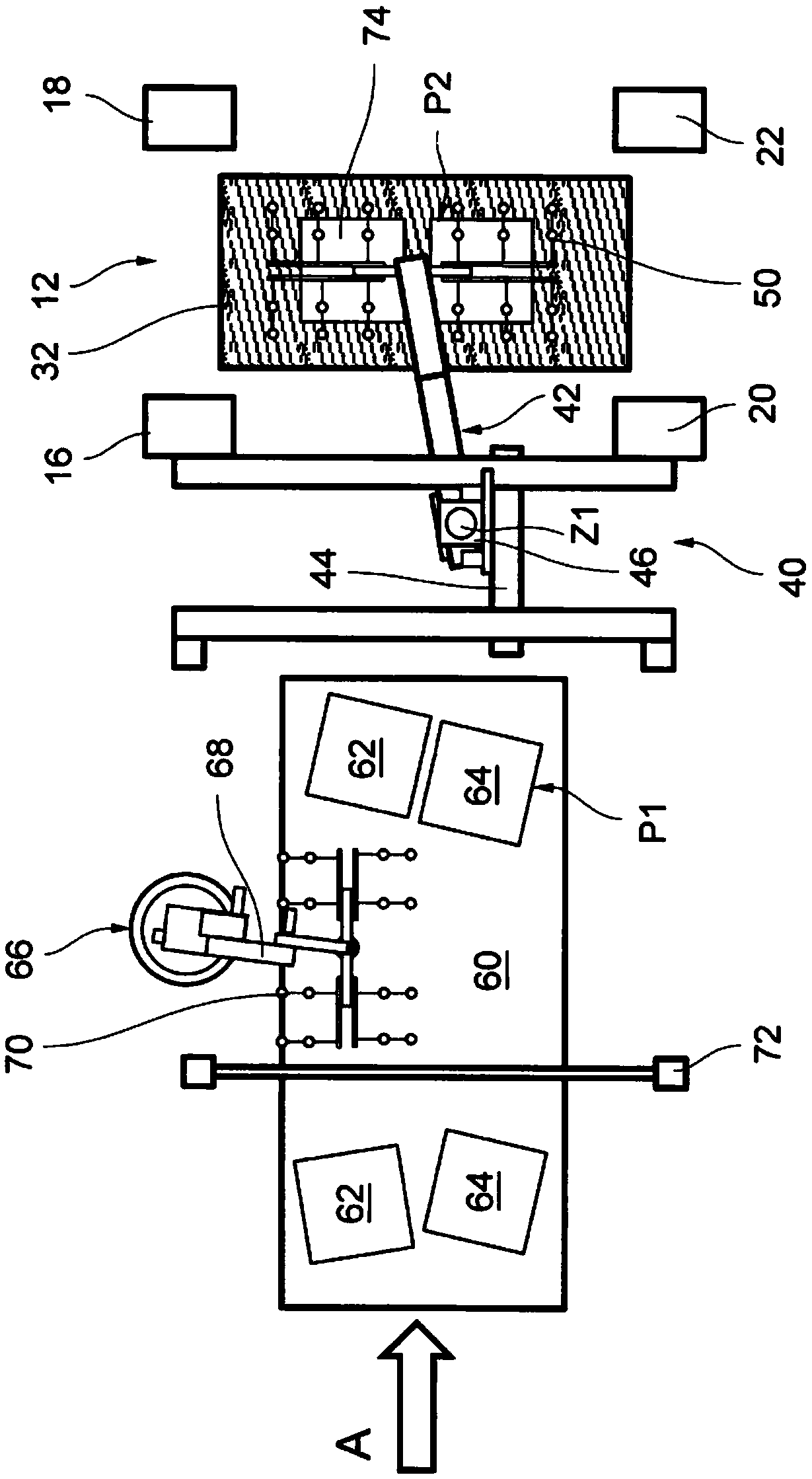
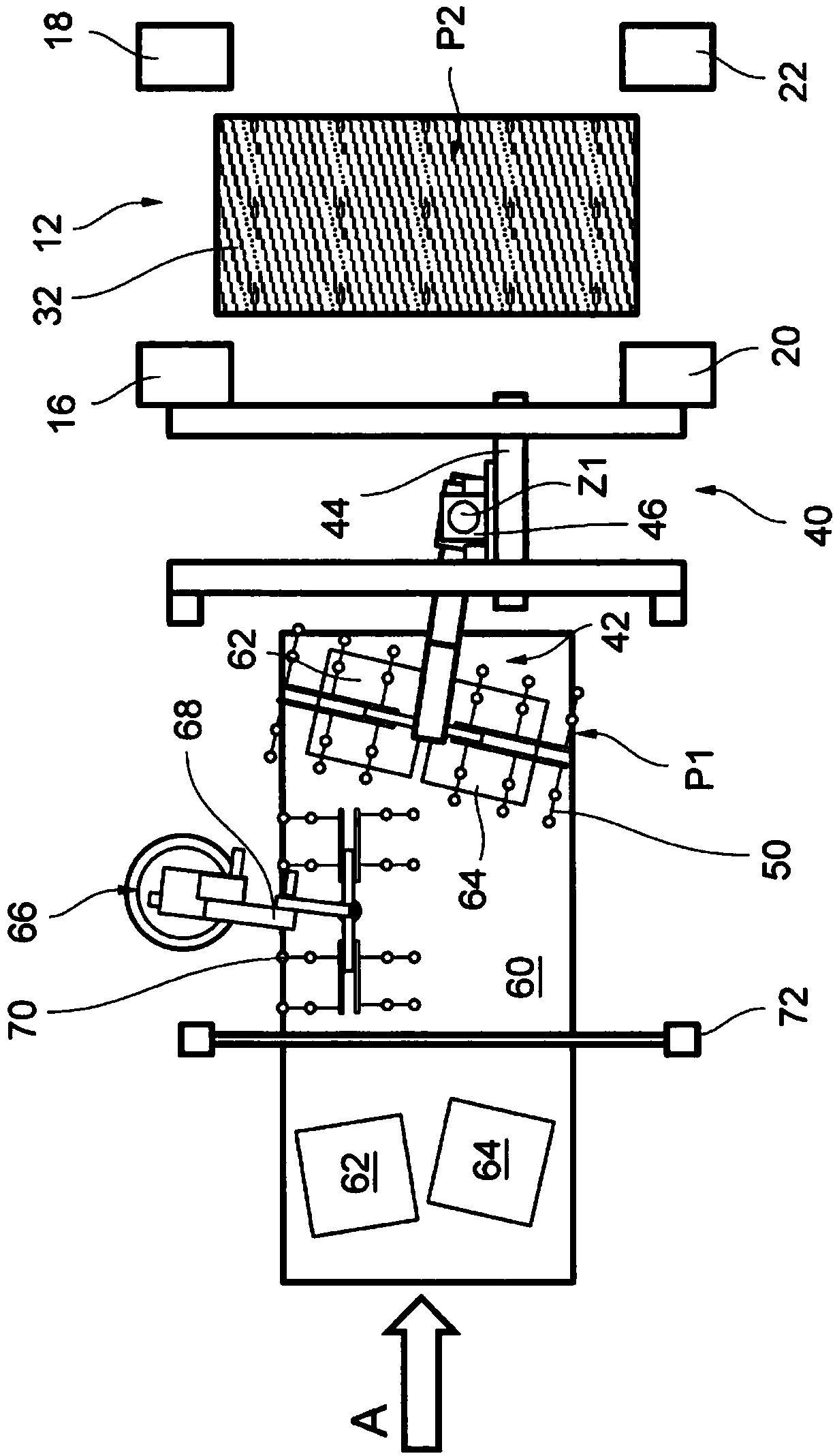
[0023] figure 1 It shows a top view of the starting area of ​​a press line, which includes a press 12 with four press supports 16, 18, 20, 22 and a bottom tool 32 arranged therein. The workpiece is punched between the bottom tool 32 and the top tool not shown and located thereon. To load the press 12, a transfer tool 40 is used, which receives the workpiece from a continuous conveyor, here a conveyor belt 60, and moves along the flow direction A (in figure 1 (Marked by an arrow) into the press 12 and placed there. For this purpose, the conveyor belt 60 transports the workpieces in the flow direction A into an area, whereby a plurality of workpieces can be simultaneously received by the transfer tool 40 from the receiving position P1 and transferred to the placement position on the bottom tool 32 of the press 12 P2. In the embodiment shown, the transfer tool 40 picks up and transfers the two workpieces 62, 64 accordingly. In addition, in figure 1 Also shown is a pair of workpi...


PUM


Abstract

The invention relates to a method for conveying and fixing workpieces (62,64), wherein the workpieces (62,64) are conveyed in a circulating direction (A) at a continuous conveying device (60), whereinin a fixing correction step, at least one first workpiece (62) is fixed relative to at least one second workpiece (64). The second workpiece keeps the position on the continuous conveying device (60)so that at least one first workpiece (62) and at least one second workpiece (64) are at the preset position. In a subsequent conveying process, at least one first workpiece (62) and at least one second workpiece (64) are simultaneously received from a receiving position (P1) by the preset position through a conveying tool (40) and is conveyed to a preset placing position (P2). The invention further relates to corresponding equipment.

Description

Technical field [0001] The invention relates to a method for conveying and positioning workpieces, and a corresponding device. Background technique [0002] In many manufacturing processes, the workpieces are successively placed in different processing stations, and the workpieces in the state of continuing processing are taken out from this processing station and transported. For example, such a processing station may involve a press in a stamping line, in which plate-shaped workpieces are processed substantially in successive stamping steps. Here, the workpiece is first conveyed in the direction of the press on the continuous conveying device, and received from the continuous conveying device and placed on the press. This continuous conveying device can involve, for example, but not limited to, a conveyor belt on which the workpieces are transported one after the other. [0003] In order to optimize the work flow and the processing speed in such a stamping production line, it i...

Claims


Application Information

Patent Timeline
IPC IPC(8): B21D43/00B21D43/02B21D43/10B21D43/12
CPCB21D43/003B21D43/02B21D43/105B21D43/12B23Q7/18B23Q17/2428
Inventor 尼哈特·德米尔安德列亚斯·森格德克·弗兰茨曼迪特马尔·凯
Owner STROTHMANN MACHINES & HANDLING
Why Eureka
Try Eureka